|
|
|
PDF CS5535 Data sheet ( Hoja de datos )
| Número de pieza | CS5535 | |
| Descripción | I/O Companion Multi-Function South Bridge | |
| Fabricantes | National Semiconductor | |
| Logotipo | ||
Hay una vista previa y un enlace de descarga de CS5535 (archivo pdf) en la parte inferior de esta página. Total 70 Páginas | ||
|
No Preview Available !
www.DataSheet4U.com
Preliminary
July 2003
Revision 0.8
Geode™ CS5535 I/O Companion
Multi-Function South Bridge
General Description
The National Semiconductor® Geode™ CS5535 is a com-
plete I/O companion for an integrated processor North
Bridge component such as the Geode GX2 processor
series. Together, the GX2 and CS5535 provide a system-
level solution well suited for the high-performance and low-
power needs of a host of information appliances that
include digital set-top boxes, personal access devices, and
thin client applications.
The internal architecture has been greatly simplified over
previous I/O companions by use of a single, high-perfor-
mance modular structure based on GeodeLink™ architec-
ture. This architecture yields high internal speed (over 4
GB/s) data movement and extremely versatile internal
power management. The GeodeLink architecture is trans-
parent to application software. Communication with the
GX2 processor is over a 33/66 MHz PCI bus.
The CS5535 incorporates many I/O functions, including
those found in typical SuperI/O chips, simplifying many
system designs. Since the graphics subsystem is entirely
contained in the GX2 processor, system interconnect is
simplified. The device contains state-of-the-art power man-
agement that enables systems, especially battery powered
systems, to significantly reduce power consumption.
Audio is supported by an internal controller, designed to
connect to multiple AC97 compatible codecs such as
National’s LM4550. An IR (infrared) port supports all popu-
lar IR communication protocols. The IR port is shared with
one of two industry-standard serial ports that can reach
speeds of 115.2 kbps. An LPC (low pin count) port is pro-
vided to facilitate connections to a SuperI/O should addi-
tional expansion, such as a floppy drive, be necessary,
and/or to an LPC ROM for the system BIOS.
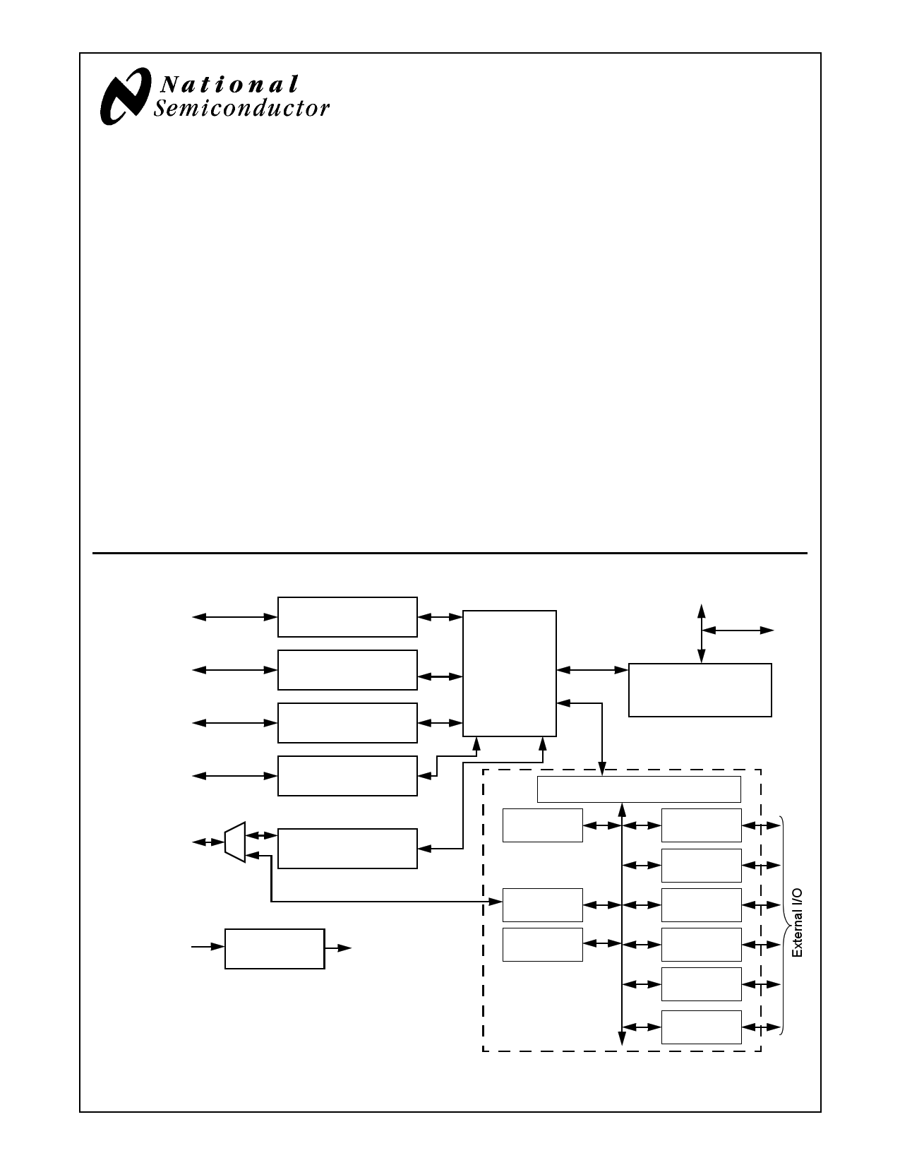
Geode™ CS5535 Block Diagram
Test/Reset
Interface
GeodeLink™ Control
Processor (GLCP)
External USB
Ports 1-1 & 1-2
USB Controller #1
(USBC1)
External USB
Ports 2-1 & 2-2
USB Controller #2
(USBC2)
External
Audio
AC97 Controller
(ACC)
External
IDE/Flash
ATA-5 Controller
(ATAC)
System Power
Voltages
Low Voltage
Detect (LVD)
Power Good
for Power On
Reset (POR)
GeodeLink™
Interface
Unit
(GLIU)
Geode™ GX2 Interface
PCI
33 or 66 MHz
GeodeLink™ PCI
South Bridge
(GLPCI_SB)
Diverse Integration Logic (DIVIL)
82xx PC
Legacy
Flash
Interface
RTC &
CMOS RAM
Diverse
Device (DD)
UART (2)
& IR (1)
SMB
Controller
LPC
Port
GPIO
Power
Mgmnt
MFGP
Timers
National Semiconductor and Virtual System Architecture are registered trademarks of National Semiconductor Corporation.
Geode, GeodeLink, MacPHYTER, WebPAD, and VSA are trademarks of National Semiconductor Corporation.
For a complete listing of National Semiconductor trademarks, please visit www.national.com/trademarks.
© 2003 National Semiconductor Corporation
www.national.com
1 page 
Table of Contents
1.0 Architecture Overview . . . . . . . . . . . . . . . . . . . . . . . . . . . . . . . . . . . . . . . . . . . . . . 12
1.1 GEODELINK PCI SOUTH BRIDGE . . . . . . . . . . . . . . . . . . . . . . . . . . . . . . . . . . . . . . . . . . . . . 13
1.2 GEODELINK CONTROL PROCESSOR . . . . . . . . . . . . . . . . . . . . . . . . . . . . . . . . . . . . . . . . . 13
1.3 ATA-5 CONTROLLER . . . . . . . . . . . . . . . . . . . . . . . . . . . . . . . . . . . . . . . . . . . . . . . . . . . . . . . . 13
1.4 UNIVERSAL SERIAL BUS CONTROLLERS . . . . . . . . . . . . . . . . . . . . . . . . . . . . . . . . . . . . . . 13
1.5 AUDIO CODEC 97 (AC97) CONTROLLER . . . . . . . . . . . . . . . . . . . . . . . . . . . . . . . . . . . . . . . 13
1.6 DIVERSE DEVICE . . . . . . . . . . . . . . . . . . . . . . . . . . . . . . . . . . . . . . . . . . . . . . . . . . . . . . . . . . 13
1.6.1 Legacy DMA . . . . . . . . . . . . . . . . . . . . . . . . . . . . . . . . . . . . . . . . . . . . . . . . . . . . . . . . 13
1.6.2 Programmable Interval Timers - Legacy Timers . . . . . . . . . . . . . . . . . . . . . . . . . . . . 14
1.6.3 Programmable Interrupt Controller - Legacy Interrupt . . . . . . . . . . . . . . . . . . . . . . . . 14
1.6.4 Keyboard Emulation Logic - Legacy Support Interface . . . . . . . . . . . . . . . . . . . . . . . 14
1.6.5 Universal Asynchronous Receiver Transmitter and IR Port . . . . . . . . . . . . . . . . . . . . 14
1.6.6 System Management Bus Controller . . . . . . . . . . . . . . . . . . . . . . . . . . . . . . . . . . . . . 14
1.6.7 Low Pin Count Port . . . . . . . . . . . . . . . . . . . . . . . . . . . . . . . . . . . . . . . . . . . . . . . . . . 14
1.6.8 General Purpose I/Os with Input Conditioning Functions (ICF) . . . . . . . . . . . . . . . . . 14
1.6.9 Multi-Function General Purpose Timers . . . . . . . . . . . . . . . . . . . . . . . . . . . . . . . . . . 15
1.6.10 Flash Interface . . . . . . . . . . . . . . . . . . . . . . . . . . . . . . . . . . . . . . . . . . . . . . . . . . . . . . 15
1.6.11 Real-Time Clock with CMOS RAM . . . . . . . . . . . . . . . . . . . . . . . . . . . . . . . . . . . . . . . 15
1.6.12 Power Management Controller . . . . . . . . . . . . . . . . . . . . . . . . . . . . . . . . . . . . . . . . . . 15
1.7 GEODELINK INTERFACE UNIT . . . . . . . . . . . . . . . . . . . . . . . . . . . . . . . . . . . . . . . . . . . . . . . 15
1.8 LOW VOLTAGE DETECT . . . . . . . . . . . . . . . . . . . . . . . . . . . . . . . . . . . . . . . . . . . . . . . . . . . . 15
1.9 PROCESSOR SUPPORT / SYSTEM OVERVIEW . . . . . . . . . . . . . . . . . . . . . . . . . . . . . . . . . 16
2.0 Signal Definitions . . . . . . . . . . . . . . . . . . . . . . . . . . . . . . . . . . . . . . . . . . . . . . . . . . 18
2.1 BALL ASSIGNMENTS . . . . . . . . . . . . . . . . . . . . . . . . . . . . . . . . . . . . . . . . . . . . . . . . . . . . . . . 19
2.1.1 Buffer Types . . . . . . . . . . . . . . . . . . . . . . . . . . . . . . . . . . . . . . . . . . . . . . . . . . . . . . . . 28
2.1.2 Boot Options . . . . . . . . . . . . . . . . . . . . . . . . . . . . . . . . . . . . . . . . . . . . . . . . . . . . . . . 29
2.1.3 Ball Options . . . . . . . . . . . . . . . . . . . . . . . . . . . . . . . . . . . . . . . . . . . . . . . . . . . . . . . . 29
2.2 SIGNAL DESCRIPTIONS . . . . . . . . . . . . . . . . . . . . . . . . . . . . . . . . . . . . . . . . . . . . . . . . . . . . 31
2.2.1 System Interface Signals . . . . . . . . . . . . . . . . . . . . . . . . . . . . . . . . . . . . . . . . . . . . . . 31
2.2.2 PCI Interface Signals () . . . . . . . . . . . . . . . . . . . . . . . . . . . . . . . . . . . . . . . . . . . . . . . 33
2.2.3 IDE/Flash Interface Signals . . . . . . . . . . . . . . . . . . . . . . . . . . . . . . . . . . . . . . . . . . . . 35
2.2.4 USB Interface . . . . . . . . . . . . . . . . . . . . . . . . . . . . . . . . . . . . . . . . . . . . . . . . . . . . . . . 38
2.2.5 System Management Bus (SMB) Interface . . . . . . . . . . . . . . . . . . . . . . . . . . . . . . . . 39
2.2.6 Low Pin Count (LPC) Interface () . . . . . . . . . . . . . . . . . . . . . . . . . . . . . . . . . . . . . . . . 40
2.2.7 Audio Codec 97 Interface . . . . . . . . . . . . . . . . . . . . . . . . . . . . . . . . . . . . . . . . . . . . . . 41
2.2.8 GPIOs . . . . . . . . . . . . . . . . . . . . . . . . . . . . . . . . . . . . . . . . . . . . . . . . . . . . . . . . . . . . 42
2.2.9 Debug and Manufacturing Test Interface . . . . . . . . . . . . . . . . . . . . . . . . . . . . . . . . . . 47
2.2.10 Power, Ground, and No Connects () . . . . . . . . . . . . . . . . . . . . . . . . . . . . . . . . . . . . . 49
3.0 Global Concepts and Features . . . . . . . . . . . . . . . . . . . . . . . . . . . . . . . . . . . . . . . 50
3.1 GEODELINK ARCHITECTURE OVERVIEW . . . . . . . . . . . . . . . . . . . . . . . . . . . . . . . . . . . . . . 50
3.1.1 Introduction . . . . . . . . . . . . . . . . . . . . . . . . . . . . . . . . . . . . . . . . . . . . . . . . . . . . . . . . 50
3.1.2 Routing . . . . . . . . . . . . . . . . . . . . . . . . . . . . . . . . . . . . . . . . . . . . . . . . . . . . . . . . . . . . 50
3.1.3 Response Packets . . . . . . . . . . . . . . . . . . . . . . . . . . . . . . . . . . . . . . . . . . . . . . . . . . . 51
3.1.4 ASMI and Error . . . . . . . . . . . . . . . . . . . . . . . . . . . . . . . . . . . . . . . . . . . . . . . . . . . . . 51
3.1.5 Topology . . . . . . . . . . . . . . . . . . . . . . . . . . . . . . . . . . . . . . . . . . . . . . . . . . . . . . . . . . . 52
3.1.6 Address Spaces and MSRs . . . . . . . . . . . . . . . . . . . . . . . . . . . . . . . . . . . . . . . . . . . . 52
3.1.7 Special Cycles and BIZZARO Flag . . . . . . . . . . . . . . . . . . . . . . . . . . . . . . . . . . . . . . 53
Revision 0.8
5 www.national.com
5 Page 
Table of Contents (Continued)
6.4 POWER SUPPLY SEQUENCE REQUIREMENTS . . . . . . . . . . . . . . . . . . . . . . . . . . . . . . . . 551
6.5 LOW VOLTAGE DETECT (LVD) PARAMETERS . . . . . . . . . . . . . . . . . . . . . . . . . . . . . . . . . . 552
7.0 Package Specifications . . . . . . . . . . . . . . . . . . . . . . . . . . . . . . . . . . . . . . . . . . . . 553
Appendix A Support Documentation . . . . . . . . . . . . . . . . . . . . . . . . . . . . . . . . . . . . 554
A.1 REVISION HISTORY . . . . . . . . . . . . . . . . . . . . . . . . . . . . . . . . . . . . . . . . . . . . . . . . . . . . . . . 554
Revision 0.8
11 www.national.com
11 Page | ||
| Páginas | Total 70 Páginas | |
| PDF Descargar | [ Datasheet CS5535.PDF ] | |
Hoja de datos destacado
| Número de pieza | Descripción | Fabricantes |
| CS5530 | Geode CS5530 I/O Companion Multi-Function South Bridge | National Semiconductor |
| CS5530 | 24-Bit ADC | Cirrus Logic |
| CS5530A | Geode CS5530A I/O Companion Multi-Function South Bridge | National Semiconductor |
| CS5530A | AMD Geode CS5530A Companion Device | Advanced Micro Devices |
| Número de pieza | Descripción | Fabricantes |
| SLA6805M | High Voltage 3 phase Motor Driver IC. |
Sanken |
| SDC1742 | 12- and 14-Bit Hybrid Synchro / Resolver-to-Digital Converters. |
Analog Devices |
|
DataSheet.es es una pagina web que funciona como un repositorio de manuales o hoja de datos de muchos de los productos más populares, |
| DataSheet.es | 2020 | Privacy Policy | Contacto | Buscar |