|
|
|
PDF LTC6804-2 Data sheet ( Hoja de datos )
| Número de pieza | LTC6804-2 | |
| Descripción | (LTC6804-1/-2) Multicell Battery Monitors | |
| Fabricantes | Linear Technology | |
| Logotipo | ||
Hay una vista previa y un enlace de descarga de LTC6804-2 (archivo pdf) en la parte inferior de esta página. Total 70 Páginas | ||
|
No Preview Available !
FEATURES
n Measures Up to 12 Battery Cells in Series
n Stackable Architecture Supports 100s of Cells
n Built-In isoSPI™ Interface:
1Mbps Isolated Serial Communications
Uses a Single Twisted Pair, Up to 100 Meters
Low EMI Susceptibility and Emissions
n 1.2mV Maximum Total Measurement Error
n 290µs to Measure All Cells in a System
n Synchronized Voltage and Current Measurement
n 16-Bit Delta-Sigma ADC with Frequency
Programmable 3rd Order Noise Filter
n Engineered for ISO26262 Compliant Systems
n Passive Cell Balancing with Programmable Timer
n 5 General Purpose Digital I/O or Analog Inputs:
Temperature or other Sensor Inputs
Configurable as an I2C or SPI Master
n 4μA Sleep Mode Supply Current
n 48-Lead SSOP Package
APPLICATIONS
n Electric and Hybrid Electric Vehicles
n Backup Battery Systems
n Grid Energy Storage
n High Power Portable Equipment
LTC6804-1/LTC6804-2
Multicell Battery Monitors
DESCRIPTION
The LTC®6804 is a 3rd generation multicell battery stack
monitor that measures up to 12 series connected battery
cells with a total measurement error of less than 1.2mV. The
cell measurement range of 0V to 5V makes the LTC6804
suitable for most battery chemistries. All 12 cell voltages
can be captured in 290µs, and lower data acquisition rates
can be selected for high noise reduction.
Multiple LTC6804 devices can be connected in series,
permitting simultaneous cell monitoring of long, high volt-
age battery strings. Each LTC6804 has an isoSPI interface
for high speed, RF-immune, local area communications.
Using the LTC6804-1, multiple devices are connected in
a daisy-chain with one host processor connection for all
devices. Using the LTC6804-2, multiple devices are con-
nected in parallel to the host processor, with each device
individually addressed.
Additional features include passive balancing for each cell,
an onboard 5V regulator, and 5 general purpose I/O lines.
In sleep mode, current consumption is reduced to 4µA.
The LTC6804 can be powered directly from the battery,http://www.DataSheet4U.net/
or from an isolated supply.
L, LT, LTC, LTM, Linear Technology and the Linear logo are registered and isoSPI is a
trademark of Linear Technology Corporation. All other trademarks are the property of their
respective owners.
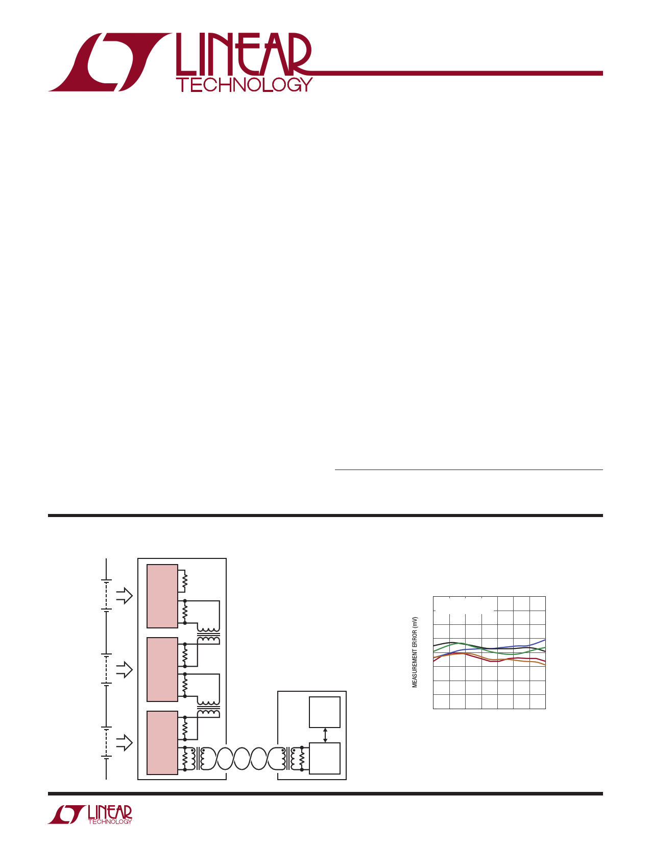
TYPICAL APPLICATION
+
12S1P
+
+
+
+
+
IPB
LTC6804-1
IMB
IPLAP
IMA
IPB
LTC6804-1
IMB
IPA
IMA
IPB
LTC6804-1
IMB
IPA
IMA
•
•
•
•
MPU
SPI
IP
LTC6820
IM
680412 TA01a
Total Measurement Error
vs Temperature of 5 Typical Units
2.0
CELL VOLTAGE = 3.3V
1.5 5 TYPICAL UNITS
1.0
0.5
0
–0.5
–1.0
–1.5
–2.0
–50 –25
0 25 50 75
TEMPERATURE (°C)
100 125
680412 TA01b
For more information www.linear.com/LTC6804-1
680412f
1
datasheet pdf - http://www.DataSheet4U.net/
1 page 
LTC6804-1/LTC6804-2
E LECTRICAL CHARACTERISTICS The l denotes the specifications which apply over the full operating
temperature range, otherwise specifications are at TA = 25°C. The test conditions are V+ = 39.6V, VREG = 5.0V unless otherwise noted.
SYMBOL
IL
PARAMETER
CONDITIONS
Total Measurement Error (TME) in C(n) to C(n – 1), GPIO(n) to V– = 0
Filtered Mode
C(n) to C(n – 1) = 2.0
C(n) to C(n – 1), GPIO(n) to V– = 2.0
C(n) to C(n – 1) = 3.3
C(n) to C(n – 1), GPIO(n) to V– = 3.3
C(n) to C(n – 1) = 4.2
C(n) to C(n – 1), GPIO(n) to V– = 4.2
C(n) to C(n – 1), GPIO(n) to V– = 5.0
Sum of Cells
Internal Temperature, T = Maximum
Specified Temperature
Total Measurement Error (TME) in
Fast Mode
VREG Pin
VREF2 Pin
Digital Supply Voltage VREGD
C(n) to C(n – 1), GPIO(n) to V– = 0
C(n) to C(n – 1), GPIO(n) to V– = 2.0
C(n) to C(n – 1), GPIO(n) to V– = 3.3
C(n) to C(n – 1), GPIO(n) to V– = 4.2
C(n) to C(n – 1), GPIO(n) to V– = 5.0
Sum of Cells
http://www.DataSheet4U.net/
Internal Temperature, T = Maximum
Specified Temperature
Input Range
VREG Pin
VREF2 Pin
Digital Supply Voltage VREGD
C(n), n = 1 to 12
C0
GPIO(n), n = 1 to 5
Input Leakage Current When Inputs C(n), n = 0 to 12
Are Not Being Measured
GPIO(n), n = 1 to 5
MIN TYP MAX
±0.1
±0.1 ±0.8
l ±1.4
±0.2 ±1.2
l ±2.2
±0.3 ±1.6
l ±2.8
±1
l ±0.2 ±0.75
±5
l ±0.1 ±0.25
l ±0.02 ±0.1
l ±0.1 ±1
±2
l ±4
l ±4.7
l ±8.3
±10
l ±0.3 ±1
±5
l ±0.3 ±1
l ±0.1 ±0.25
l ±0.2 ±2
l C(n – 1)
C(n – 1) + 5
l0
l0
5
l 10 ±250
l 10 ±250
UNITS
mV
mV
mV
mV
mV
mV
mV
mV
%
°C
%
%
%
mV
mV
mV
mV
mV
%
°C
%
%
%
V
V
nA
nA
Input Current When Inputs Are
Being Measured
Input Current During Open Wire
Detection
C(n), n = 0 to 12
GPIO(n), n = 1 to 5
±2
±2
l 70 100 130
µA
µA
µA
For more information www.linear.com/LTC6804-1
680412f
5
datasheet pdf - http://www.DataSheet4U.net/
5 Page 
LTC6804-1/LTC6804-2
TYPICAL PERFORMANCE CHARACTERISTICS TA = 25°C, unless otherwise noted.
Measurement Gain Error
Hysteresis, Hot
25 TA = 85°C TO 25°C
20
15
10
5
Measurement Gain Error
Hysteresis, Cold
30 TA = –45°C TO 25°C
25
20
15
10
5
Noise Filter Response
0
–10
–20
–30
–40
–50
–60
0
–50 –40 –30 –20 –10 0 10 20
CHANGE IN GAIN ERROR (ppm)
30
680412 G10
0
–40 –30 –20 –10 0 10 20 30
CHANGE IN GAIN ERROR (ppm)
40
680412 G11
–70
10
100 1k 10k 100k
INPUT FREQUENCY (Hz)
1M
ADC MODE:
FILTERED
2kHz
3kHz
NORMAL
15kHz
FAST 680412 G12
Measurement Error vs VREG
2.0
1.5
1.0
0.5
0
–0.5
–1.0
VIN = 2V
–1.5 VIN = 3.3V
VIN = 4.2V
–2.0
4.5 4.6 4.7 4.8 4.9 5.0 5.1 5.2 5.3 5.4 5.5
VREG (V)
680412 G13
Cell Measurement Error
vs Input RC Values
20
NORMAL MODE CONVERSIONS
15 DIFFERENTIAL RC FILTER ON EVERY C PIN.
EXPECT CELL-TO-CELL AND
10
PART-TO-PART VARIATIONS
IN ERROR IF R > 100Ω AND/OR C > 10nF
5
0
–5
–10
–15
–20
1
C=0
C = 10nF
C = 100nF
C = 1µF
10 100 1000
INPUT RESISTOR, R (Ω)
10000
680412 G16
Measurement Error V+ PSRR
vs Frequency
–40
–45
VV++DACC
=
=
39.6V
5VP-P
–50
1 BIT CHANGE < –90dB
VREG GENERATED FROM
–55 DRIVE PIN, FIGURE 28
http://www.DataSheet4U.net/
–60
–65
–70
–75
–80
–85
–90
100
1k 10k 100k 1M
FREQUENCY (Hz)
10M
680412 G14
GPIO Measurement Error
vs Input RC Values
10 TIME BETWEEN MEASUREMENTS > 3RC
8
6
4
2
0
–2
–4
–6
–8
–10
1
C=0
C = 100nF
C = 1µF
C = 10µF
10 100 1000 10000 100000
INPUT RESISTANCE, R (Ω)
680412 G17
For more information www.linear.com/LTC6804-1
Measurement Error VREG PSRR
vs Frequency
0
VREG(DC) = 5V
–10
VREG(AC) = 500mVP-P
1 BIT CHANGE < –70dB
–20
–30
–40
–50
–60
–70
100
1k 10k 100k 1M
FREQUENCY (Hz)
10M
68412 G15
Top Cell Measurement Error vs V+
1.0
0.8
C12-C11 = 3.3V
C12 = 39.6V
0.6
0.4
0.2
0
–0.2
–0.4
–0.6
–0.8
–1.0
36
38 40 42
V+ (V)
44
680412 G18
680412f
11
datasheet pdf - http://www.DataSheet4U.net/
11 Page | ||
| Páginas | Total 70 Páginas | |
| PDF Descargar | [ Datasheet LTC6804-2.PDF ] | |
Hoja de datos destacado
| Número de pieza | Descripción | Fabricantes |
| LTC6804-1 | (LTC6804-1/-2) Multicell Battery Monitors | Linear Technology |
| LTC6804-2 | (LTC6804-1/-2) Multicell Battery Monitors | Linear Technology |
| Número de pieza | Descripción | Fabricantes |
| SLA6805M | High Voltage 3 phase Motor Driver IC. |
Sanken |
| SDC1742 | 12- and 14-Bit Hybrid Synchro / Resolver-to-Digital Converters. |
Analog Devices |
|
DataSheet.es es una pagina web que funciona como un repositorio de manuales o hoja de datos de muchos de los productos más populares, |
| DataSheet.es | 2020 | Privacy Policy | Contacto | Buscar |