|
|
|
PDF LM20323A Data sheet ( Hoja de datos )
| Número de pieza | LM20323A | |
| Descripción | 3A 500 kHz Synchronous Buck Regulator | |
| Fabricantes | National Semiconductor | |
| Logotipo | ||
Hay una vista previa y un enlace de descarga de LM20323A (archivo pdf) en la parte inferior de esta página. Total 20 Páginas | ||
|
No Preview Available !
www.DataSheet4U.com
January 20, 2009
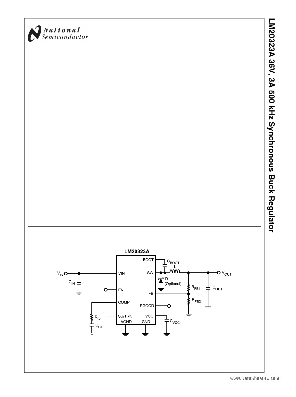
LM20323A
36V, 3A 500 kHz Synchronous Buck Regulator
General Description
The LM20323A is a full featured 500kHz synchronous buck
regulator capable of delivering up to 3A of load current. The
current mode control loop is externally compensated with only
two components, offering both high performance and ease of
use. The device is optimized to work over the input voltage
range of 4.5V to 36V making it well suited for high voltage
systems.
The device features internal Over Voltage Protection (OVP)
and Over Current Protection (OCP) circuits for increased sys-
tem reliability. A precision Enable pin and integrated UVLO
allows the turn-on of the device to be tightly controlled and
sequenced. Startup inrush currents are limited by both an in-
ternally fixed and externally adjustable soft-start circuit. Fault
detection and supply sequencing are possible with the inte-
grated power good (PGOOD) circuit.
The LM20323A is designed to work well in multi-rail power
supply architectures. The output voltage of the device can be
configured to track a higher voltage rail using the SS/TRK pin.
If the output of the LM20323A is pre-biased at startup it will
not sink current to pull the output low until the internal soft-
start ramp exceeds the voltage at the feedback pin.
The LM20323A is offered in an exposed pad 20-pin eTSSOP
package that can be soldered to the PCB, eliminating the
need for bulky heatsinks.
Features
■ 4.5V to 36V input voltage range
■ 3A output current, 5.2A peak current
■ 130 mΩ/110 mΩ integrated power MOSFETs
■ 93% peak efficiency with synchronous rectification
■ 1.0% feedback voltage accuracy
■ Current mode control, selectable compensation
■ Fixed 500 kHz switching frequency
■ Adjustable output voltage down to 0.8V
■ Compatible with pre-biased loads
■ Programmable soft-start with external capacitor
■ Precision enable pin with hysteresis
■ Integrated OVP, UVLO, PGOOD
■ Internally protected with peak current limit, thermal
shutdown and restart
■ Accurate current limit minimizes inductor size
■ Non-linear current mode slope compensation
■ eTSSOP-20 exposed pad package
Applications
■ Simple to design, high efficiency point of load regulation
from a 4.5V to 36V bus
■ High Performance DSPs, FPGAs, ASICs and
Microprocessors
■ Communications Infrastructure, Automotive
Simplified Application Circuit
PowerWise® is a registered trademark of National Semiconductor Corporation.
© 2009 National Semiconductor Corporation 300772
30077201
www.national.com
1 page 
www.DataSheet4U.comError Amplifier Phase
Line Regulation
Load Regulation
30077206
VCC vs. VIN
30077207
Non-Switching IQ vs. VIN
30077286
Shutdown IQ vs. VIN
30077208
30077209
5
30077210
www.national.com
5 Page 
LM20323A tri-states the power FETs and resets soft-start.
wwAwfte.DrathtaeSjuhneceti4oUn.coomls to approximately 150°C, the part starts
up using the normal start up routine. This feature is provided
to prevent catastrophic failures from accidental device over-
heating.
Design Guide
This section walks the designer through the steps necessary
to select the external components to build a fully functional
power supply. As with any DC-DC converter numerous trade-
offs are possible to optimize the design for efficiency, size, or
performance. These will be taken into account and highlight-
ed throughout this discussion. To facilitate component selec-
tion discussions the circuit shown in Figure 1 below may be
used as a reference. Unless otherwise indicated, all formulas
assume units of amps (A) for current, farads (F) for capaci-
tance, henries (H) for inductance and volts (V) for voltages.
FIGURE 1. Typical Application Circuit
The first equation to calculate for any buck converter is duty-
cycle. Ignoring conduction losses associated with the FETs
and parasitic resistances it can be approximated by:
30077229
INDUCTOR SELECTION (L)
The inductor value is determined based on the operating fre-
quency, load current, ripple current and duty cycle.
The inductor selected should have a saturation current rating
greater than the peak current limit of the device. Keep in mind
the specified current limit does not account for delay of the
current limit comparator, therefore the current limit in the ap-
plication may be higher than the specified value. To optimize
the performance and prevent the device from entering current
limit at maximum load, the inductance is typically selected
such that the ripple current, ΔiL, is not greater than 30% of the
rated output current. Figure 2 illustrates the switch and in-
ductor ripple current waveforms. Once the input voltage, out-
put voltage, operating frequency and desired ripple current
are known, the minimum value for the inductor can be calcu-
lated by the formula shown below:
30077267
FIGURE 2. Switch and Inductor Current Waveforms
If needed, slightly smaller value inductors can be used, how-
ever, the peak inductor current, IOUT + ΔiL/2, should be kept
below the peak current limit of the device. In general, the in-
ductor ripple current, ΔiL, should be more than 10% of the
rated output current to provide adequate current sense infor-
mation for the current mode control loop. If the ripple current
in the inductor is too low, the control loop will not have suffi-
cient current sense information and can be prone to instability.
OUTPUT CAPACITOR SELECTION (COUT)
The output capacitor, COUT, filters the inductor ripple current
and provides a source of charge for transient load conditions.
A wide range of output capacitors may be used with the
LM20323A that provide excellent performance. The best per-
formance is typically obtained using ceramic, SP or OSCON
type chemistries. Typical trade-offs are that the ceramic ca-
pacitor provides extremely low ESR to reduce the output
ripple voltage and noise spikes, while the SP and OSCON
11 www.national.com
11 Page | ||
| Páginas | Total 20 Páginas | |
| PDF Descargar | [ Datasheet LM20323A.PDF ] | |
Hoja de datos destacado
| Número de pieza | Descripción | Fabricantes |
| LM20323 | LM20323 36V 3A 500 kHz Synchronous Buck Regulator (Rev. C) | Texas Instruments |
| LM20323 | 500 kHz Synchronous Buck Regulator | National Semiconductor |
| LM20323A | 3A 500 kHz Synchronous Buck Regulator | National Semiconductor |
| Número de pieza | Descripción | Fabricantes |
| SLA6805M | High Voltage 3 phase Motor Driver IC. |
Sanken |
| SDC1742 | 12- and 14-Bit Hybrid Synchro / Resolver-to-Digital Converters. |
Analog Devices |
|
DataSheet.es es una pagina web que funciona como un repositorio de manuales o hoja de datos de muchos de los productos más populares, |
| DataSheet.es | 2020 | Privacy Policy | Contacto | Buscar |