|
|
|
PDF IRFH7914PBF Data sheet ( Hoja de datos )
| Número de pieza | IRFH7914PBF | |
| Descripción | Power MOSFET ( Transistor ) | |
| Fabricantes | International Rectifier | |
| Logotipo | ||
Hay una vista previa y un enlace de descarga de IRFH7914PBF (archivo pdf) en la parte inferior de esta página. Total 9 Páginas | ||
|
No Preview Available !
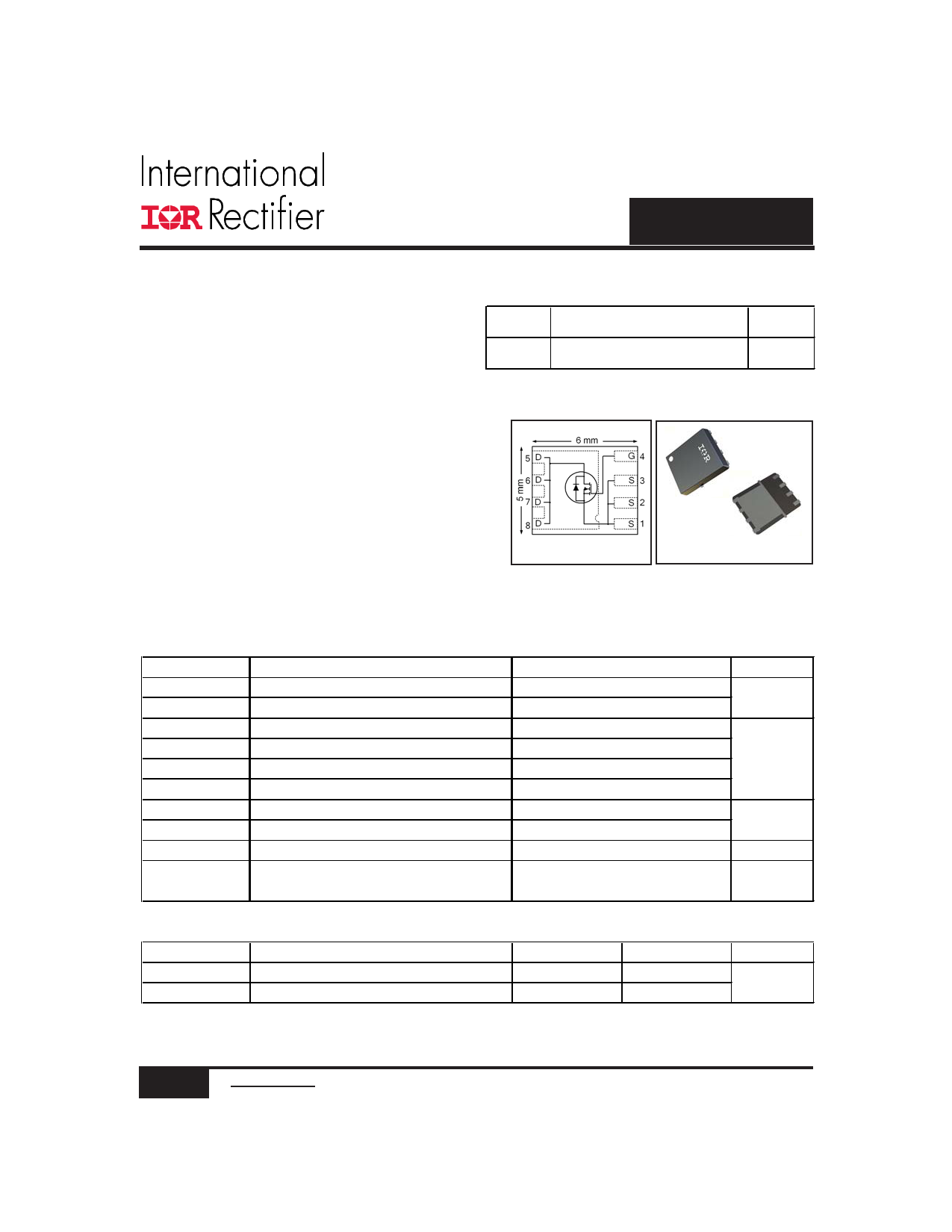
IRFH7914PbF
Applications
l Control MOSFET of Sync-Buck Converters
used for Notebook Processor Power
l Control MOSFET for Isolated DC-DC
Converters in Networking Systems
VDSS
30V
HEXFET® Power MOSFET
RDS(on) max
Qg
8.7mΩ@VGS = 10V 8.3nC
Benefits
l Very low RDS(ON) at 4.5V VGS
l Low Gate Charge
l Fully Characterized Avalanche Voltage and
Current
l 100% Tested for RG
l Lead-Free (Qualified up to 260°C Reflow)
l RoHS compliant (Halogen Free)
l Low Thermal Resistance
l Large Source Lead for more reliable Soldering
PQFN 5X6 mm
Absolute Maximum Ratings
Parameter
VDS Drain-to-Source Voltage
VGS
ID @ TA = 25°C
ID @ TA = 70°C
ID @ TC = 25°C
IDM
PD @TA = 25°C
PD @TA = 70°C
TJ
Gate-to-Source Voltage
Continuous Drain Current, VGS @ 10V
Continuous Drain Current, VGS @ 10V
Continuous Drain Current, VGS @ 10V
cPulsed Drain Current
gPower Dissipation
gPower Dissipation
gLinear Derating Factor
Operating Junction and
TSTG
Storage Temperature Range
Thermal Resistance
Parameter
fRθJC
gRθJA
Junction-to-Case
Junction-to-Ambient
Notes through
are on page 9
Max.
30
± 20
15
12
35
110
3.1
2.0
0.025
-55 to + 150
Units
V
A
W
W/°C
°C
Typ.
–––
–––
Max.
7.2
40
Units
°C/W
1 www.irf.com © 2013 International Rectifier
August 16, 2013
1 page 
IRFH7914PbF
16
14
12
10
8
6
4
2
0
25
50 75 100 125
TA , Ambient Temperature (°C)
150
2.5
2.0
1.5 ID = 25µA
1.0
0.5
-75 -50 -25 0 25 50 75 100 125 150
TJ , Temperature ( °C )
Fig 9. Maximum Drain Current vs.
Ambient Temperature
Fig 10. Threshold Voltage vs. Temperature
100
D = 0.50
10 0.20
0.10
0.05
1 0.02
0.01
0.1
τJ τJ
τ1 τ1
R 1R 1
CiC= iτ=i/τRi/iRi
R 2R 2
τ2 τ2
R 3R 3
τ3 τ3
0.01
1E-006
SINGLE PULSE
( THERMAL RESPONSE )
1E-005 0.0001
0.001
0.01
0.1
1
t1 , Rectangular Pulse Duration (sec)
R4R4 Ri (°C/W) τi (sec)
τ4 τ4
τAτA
2.0021
6.0077
15.5002
0.000245
0.014521
0.7719
16.4970 38.3
Notes:
1. Duty Factor D = t1/t2
2. Peak Tj = P dm x Zthja + T A
10 100 1000
Fig 11. Maximum Effective Transient Thermal Impedance, Junction-to-Ambient
5 www.irf.com © 2013 International Rectifier
August 16, 2013
5 Page | ||
| Páginas | Total 9 Páginas | |
| PDF Descargar | [ Datasheet IRFH7914PBF.PDF ] | |
Hoja de datos destacado
| Número de pieza | Descripción | Fabricantes |
| IRFH7914PBF | Power MOSFET ( Transistor ) | International Rectifier |
| Número de pieza | Descripción | Fabricantes |
| SLA6805M | High Voltage 3 phase Motor Driver IC. |
Sanken |
| SDC1742 | 12- and 14-Bit Hybrid Synchro / Resolver-to-Digital Converters. |
Analog Devices |
|
DataSheet.es es una pagina web que funciona como un repositorio de manuales o hoja de datos de muchos de los productos más populares, |
| DataSheet.es | 2020 | Privacy Policy | Contacto | Buscar |