|
|
|
PDF XR20V2170 Data sheet ( Hoja de datos )
| Número de pieza | XR20V2170 | |
| Descripción | I2C/SPI UART | |
| Fabricantes | Exar Corporation | |
| Logotipo | ||
Hay una vista previa y un enlace de descarga de XR20V2170 (archivo pdf) en la parte inferior de esta página. Total 30 Páginas | ||
|
No Preview Available !
www.DataSheet4U.com
XR20V2170
I2C/SPI UART WITH 64-BYTE FIFO AND RS232 TRANSCEIVER
JUNE 2007
REV. 1.0.0
GENERAL DESCRIPTION
The XR20V21701 (V2170) is a high performance
universal asynchronous receiver and transmitter
(UART) with 64 byte TX and RX FIFOs, a selectable
I2C/SPI slave interface and RS232 transceiver. The
V2170 operates from 2.97 to 3.63 volts. The
enhanced features in the V2170 include a
programmable fractional baud rate generator, an 8X
and 4X sampling rate that allows for a maximum baud
rate of 250 Kbps at 3.3V. The standard features
include 16 selectable TX and RX FIFO trigger levels,
automatic hardware (RTS/CTS) and software (Xon/
Xoff) flow control, and a complete modem interface.
Onboard registers provide the user with operational
status and data error flags. An internal loopback
capability allows system diagnostics. The V2170 is
available in the 40-pin QFN.
NOTE: 1 Covered by U.S. Patent #5,649,122
APPLICATIONS
• Portable Appliances
• Battery-Operated Devices
• Cellular Data Devices
• Factory Automation and Process Controls
FEATURES
• Selectable I2C/SPI Interface
• Meets true EIA/TIA-232-F Standards from +2.97V
to +3.63V operation
• Data rate up to 250 Kbps
• 45us sleep mode exit (charge pump to full power)
• ESD protection for RS-232 I/O pins at
■ +/-15kV - Human Body Model
■ +/-15kV - IEC 61000-4-2, Air-Gap Discharge
■ +/- 8kV - IEC 61000-4-2, Contact Discharge
• Full-featured UART
■ Fractional Baud Rate Generator
■ Transmit and Receive FIFOs of 64 bytes
■ 16 Selectable TX and RX FIFO Trigger Levels
■ Automatic Hardware (RTS/CTS) Flow Control
■ Automatic Software (Xon/Xoff) Flow Control
■ Halt and Resume Transmission Control
■ Automatic sleep mode
■ General Purpose I/Os
■ Full modem interface
• 40-QFN packages
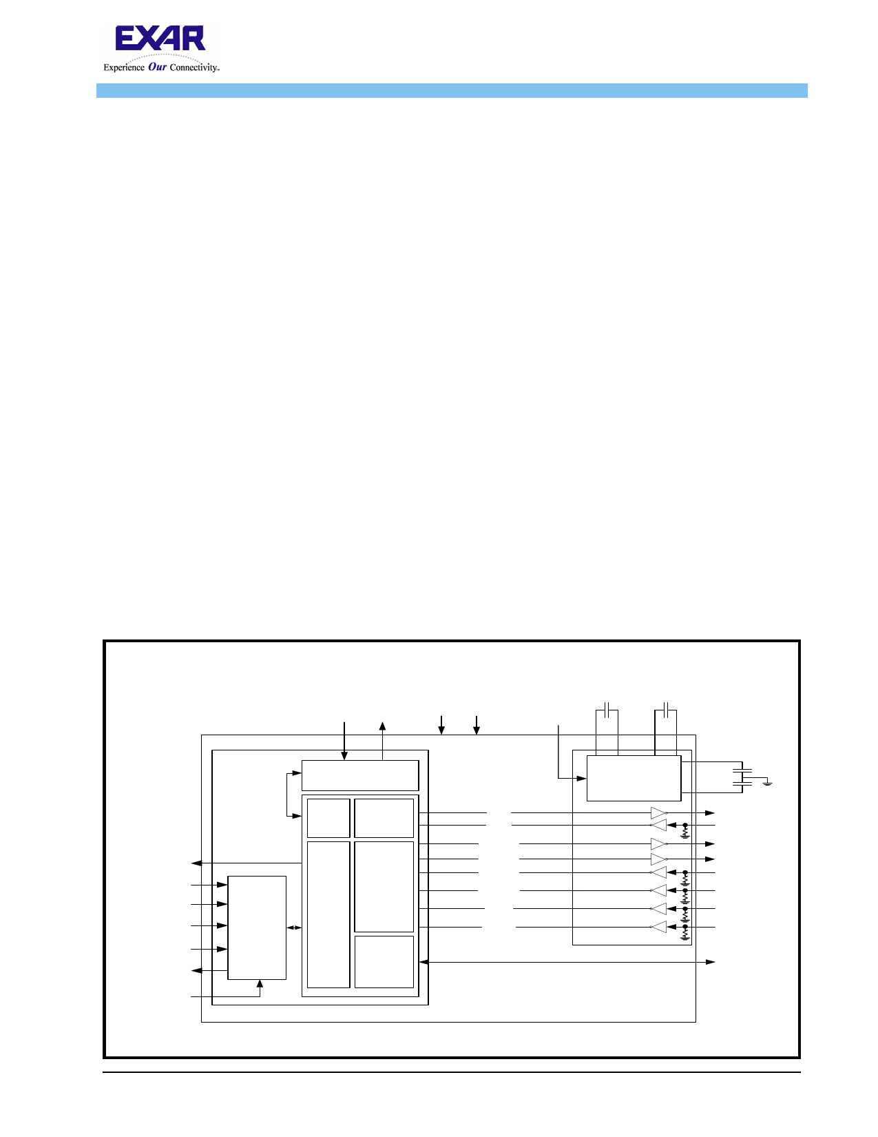
FIGURE 1. XR20V2170 BLOCK DIAGRAM
IR Q #
SDA
SCK
A 0/C S#
A 1 /S I
SO
I2C /SP I#
C rystal
O sc / Buffer
BRG
64 Byte
TX & RX
F IF O
I2 C /S P I
In te rfa c e
M odem
I/O s
G PIO s
TX
RX
RTS#
DTR #
CTS#
DSR #
RI#
CD#
UART
X R20V 2170
Charge Pum p
5K
5K
5K
5K
5K
R S -232 Transceiver
VREF+
VREF-
TXD
RXD
RTS
DTR
CTS
DSR
RI
CD
G P IO [3:0]
Exar Corporation 48720 Kato Road, Fremont CA, 94538 • (510) 668-7000 • FAX (510) 668-7017 • www.exar.com
1 page 
XR20V2170
REV. 1.0.0
I2C/SPI UART WITH 64-BYTE FIFO AND RS232 TRANSCEIVER
1.0 PRODUCT DESCRIPTION
The XR20V2170 (V2170) integrates a selectable I2C/SPI bus interface with an enhanced Universal
Asynchronous Receiver and Transmitter (UART) and an RS-232 Transceiver. The configuration registers set is
16550 UART compatible for control, status and data transfer. Additionally, the V2170 has 64-bytes of transmit
and receive FIFOs, automatic RTS/CTS hardware flow control, automatic Xon/Xoff and special character
software flow control, programmable transmit and receive FIFO trigger levels, programmable fractional baud
rate generator with a prescaler of divide by 1 or 4, data rate up to 250 kbps, while meeting all EIA RS-232F
specifications. Additionally, the V2170 includes the ACP pin which the user can shut down the charge pump for
the RS-232 drivers when the V2170 is already in sleep mode. The Power-Save feature further isolates the
databus interface to further reduce power consumption in the sleep mode. The XR20V2170 is a 2.97V to 3.63V
device. The V2170 is fabricated with an advanced CMOS process.
Enhanced Features
The V2170 UART provides a solution that supports 64 bytes of transmit and receive FIFO memory, instead of
16 bytes in the industry standard 16C550. The V2170 is designed to work with low supply voltage and high
performance data communication systems, that require fast data processing time. Increased performance is
realized in the V2170 by the larger transmit and receive FIFOs, FIFO trigger level control and automatic flow
control mechanism. This allows the external processor to handle more networking tasks within a given time.
For example, the 16C550 with a 16 byte FIFO, unloads 16 bytes of receive data in 1.53 ms (This example uses
a character length of 11 bits, including start/stop bits at 115.2 Kbps). This means the external CPU will have to
service the receive FIFO at 1.53 ms intervals. However with the 64 byte FIFO in the V2170, the data buffer will
not require unloading/loading for 6.1 ms. This increases the service interval giving the external CPU additional
time for other applications and reducing the overall UART interrupt servicing time. In addition, the
programmable FIFO level trigger interrupt and automatic hardware/software flow control is uniquely provided
for maximum data throughput performance especially when operating in a multi-channel system. The
combination of the above greatly reduces the CPU’s bandwidth requirement, increases performance, and
reduces power consumption. Finally, since the V2170 includes an RS-232 transceiver and a full-modem
interface, it can be connected to an RS-232 serial cable directly.
Data Rate
The V2170 is capable of operation up to 250 Kbps data rate using the 16X, 8X or 4X internal sampling clock
rate. The UART section can operate at much higher speeds, but the speed of the RS-232 transceiver is limited
to 250Kbps beyond which the V2170 cannot comply with the EIA/TIA-232 electrical characteristics. The device
can operate either with a crystal on pins XTAL1 and XTAL2, or external clock source on XTAL1 pin.
RS-232 Interface
The V2170 includes RS-232 drivers/receivers for the modem interface. This feature eliminates the need for an
external RS-232 transceiver. The charge pump provides output voltages of +5V and -5V for its drivers over the
2.97V to 3.63V power supply voltage range. The serial outputs TXD swing between -5V (inactive) and +5V
(active) RS-232 voltage levels. The serial inputs RXD are RS-232 receivers and can take any voltage swing
from -15V to +15V. The receivers are always active, even in Sleep mode. The RS-232 drivers guarantee a data
rate of 250 Kbps even when fully loaded with 3Kohm in parallel with 1000pF load.
All RS-232 drivers and receivers are protected to ±15kV using the Human Body Model ground combination,
±8kV using IEC 61000-4-2 Contact Discharge, and ±15kV using IEC 61000-4-2 Air-Gap Discharge. For more
information, send an e-mail to [email protected].
5
5 Page 
XR20V2170
REV. 1.0.0
I2C/SPI UART WITH 64-BYTE FIFO AND RS232 TRANSCEIVER
value of ’1’ (DLL = 0x01, DLM = 0x00 and DLD = 0x00) upon reset. Therefore, the BRG must be programmed
during initialization to the operating data rate. The DLL and DLM registers provide the integer part of the divisor
and the DLD register provides the fractional part of the dvisior. The four lower bits of the DLD are used to select
a value from 0 (for setting 0000) to 0.9375 or 15/16 (for setting 1111). Programming the Baud Rate Generator
Registers DLL, DLM and DLD provides the capability for selecting the operating data rate. Table 6 shows the
standard data rates available with a 24MHz crystal or external clock at 16X clock rate. If the pre-scaler is used
(MCR bit-7 = 1), the output data rate will be 4 times less than that shown in Table 6. At 8X sampling rate, these
data rates would double and at 4X sampling rate, these data rates would quadruple. Also, when using 8X
sampling mode, the bit time will have a jitter of ± 1/16 whenever the DLD is non-zero and is an odd number.
When using 4X sampling mode, the bit time will have a jitter of ± 1/8 whenever DLD is non-zero, odd and not a
multiple of 4. When using a non-standard data rate crystal or external clock, the divisor value can be
calculated with the following equation(s):
Required Divisor (decimal)=(XTAL1 clock frequency / prescaler) /(serial data rate x 16), with 16X mode, DLD[5:4]=’00’
Required Divisor (decimal)= (XTAL1 clock frequency / prescaler / (serial data rate x 8), with 8X mode, DLD[5:4] = ’01’
Required Divisor (decimal)= (XTAL1 clock frequency / prescaler / (serial data rate x 4), with 4X mode, DLD[5:4] = ’10’
The closest divisor that is obtainable in the V2170 can be calculated using the following formula:
ROUND( (Required Divisor - TRUNC(Required Divisor) )*16)/16 + TRUNC(Required Divisor), where
DLM = TRUNC(Required Divisor) >> 8
DLL = TRUNC(Required Divisor) & 0xFF
DLD = ROUND( (Required Divisor-TRUNC(Required Divisor) )*16)
In the formulas above, please note that:
TRUNC (N) = Integer Part of N. For example, TRUNC (5.6) = 5.
ROUND (N) = N rounded towards the closest integer. For example, ROUND (7.3) = 7 and ROUND (9.9) = 10.
A >> B indicates right shifting the value ’A’ by ’B’ number of bits. For example, 0x78A3 >> 8 = 0x0078.
FIGURE 8. BAUD RATE GENERATOR
XTAL1
XTAL2
Crystal
Osc/
Buffer
Prescaler
Divide by 1
Prescaler
Divide by 4
DLL, DLM and DLD
Registers
MCR Bit-7=0
(default)
Fractional Baud
Rate Generator
Logic
16X or 8X or 4X
Sampling
Rate Clock
to Transmitter
and Receiver
MCR Bit-7=1
11
11 Page | ||
| Páginas | Total 30 Páginas | |
| PDF Descargar | [ Datasheet XR20V2170.PDF ] | |
Hoja de datos destacado
| Número de pieza | Descripción | Fabricantes |
| XR20V2170 | I2C/SPI UART | Exar Corporation |
| XR20V2172 | TWO CHANNEL I2C/SPI UART | Exar Corporation |
| Número de pieza | Descripción | Fabricantes |
| SLA6805M | High Voltage 3 phase Motor Driver IC. |
Sanken |
| SDC1742 | 12- and 14-Bit Hybrid Synchro / Resolver-to-Digital Converters. |
Analog Devices |
|
DataSheet.es es una pagina web que funciona como un repositorio de manuales o hoja de datos de muchos de los productos más populares, |
| DataSheet.es | 2020 | Privacy Policy | Contacto | Buscar |