|
|
|
PDF SP6649EU Data sheet ( Hoja de datos )
| Número de pieza | SP6649EU | |
| Descripción | Ultra-low Quiescent Current / High Efficiency Boost DC-DC Regulator | |
| Fabricantes | Sipex | |
| Logotipo | ||
Hay una vista previa y un enlace de descarga de SP6649EU (archivo pdf) en la parte inferior de esta página. Total 9 Páginas | ||
|
No Preview Available !
® SP6649
Ultra-low Quiescent Current,
High Efficiency Boost DC-DC Regulator
FEATURES
■ Ultra-low 12µA Quiescent Current
■ 700mA Output Current at 2.6VIN, 3.3VOUT
■ 94% Efficiency Possible
■ Wide Input Voltage Range: 0.85V to 4.5V
■ 3.3V Fixed Output and adjustable 2.5V to
5.0V Output Range
■ Internal Synchronous Rectifier for High
Efficiency
■ 0.3 Charging Switch, 0.3 Synchro-
nous Rectifier
■ Anti-Ringing Inductor Switch
■ Programmable Inductor Peak Current
■ Logic Shutdown Control
■ Under Voltage Lock-Out, 0.62V
■ Programmable Low Battery Detect
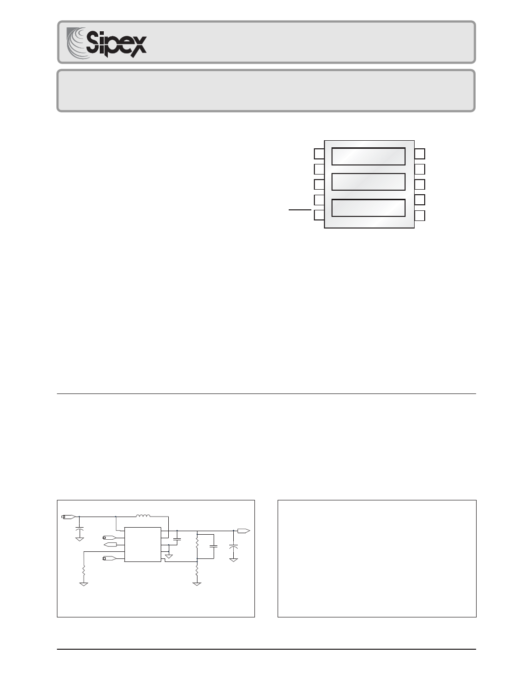
■ Small 10 pin MSOP Package
VBATT 1
LBI 2
LBON 3
RLIM 4
SHDN 5
Top View
10 pin MSOP
Tja=113°C/W
10 VOUT
9 LX
8 PGND
7 GND
6 FB
APPLICATIONS
■ Digital Still Cameras
■ MP3 Players
■ PDA's
■ Pagers
■ Handheld Portable Devices
■ Medical Monitors
DESCRIPTION
The SP6649 is an ultra-low quiescent current, high efficiency step-up DC-DC converter ideal for
single and dual cell alkaline, or Li-Ion battery applications such as digital still cameras, PDA’s,
MP3 players, and other portable devices. The SP6649 combines the high delivery associated
with PWM control, and the low quiescent current and excellent light-load efficiency of PFM control.
The SP6649 features 12µA quiescent current, synchronous rectification, a 0.3 charging switch,
anti-ringing inductor switch, programmable low battery detect, under-voltage lockout and
programmable inductor peak current. The device can be controlled by a 1nA active LOW
shutdown pin.
VBATT
C1
+
47uF
LBI
LBON
SHDN
RLIM
1.87K
L1 10uH
1 VBATT
VOUT 10
2 LBI SP6649 LX 9
3 LBON
PGND 8
4
RLIM
7
GND
5
SHDN
6
FB
3.3Vout
C4
1uF
R1
205K
C3
47pF
+ C2
47uF
R2
124K
C1 = C2 = Kemet T49C476K010AS, L1 = Sumida CDRH5D28-100
R1 = 374K for 5VOUT
Figure 1. Typical Application Circuit
TBD
Figure 2. Maximum Load Current in Operation
Rev:001 Date:11/20/03
SP6649 Ultra-low Quiescent Current, High Efficiency Boost DC-DC Regulator
1
© Copyright 2002 Sipex Corporation
1 page 
At light loads (plot A in Figure 3) the charge
cycle will take tON, MAX µs. For a 1V battery this
would be:
tON, MAX = KON / VBATT = 3.3Vµs / 1V = 3.3µs
The current built up in the coil during the charge
cycle gets fully discharged (discontinuous con-
duction mode, DCM) When the current in the
coil has reached zero the synchronous rectifier
switch is opened and the voltage across the coil
(from VBATT to LX) is shorted internally to
eliminate inductive ringing.
With increasing load (plot B in Figure 3) this
inductor damping time becomes shorter (be-
cause the output will drop quicker below its
regulation point due to the heavier load) up to
the point where it becomes zero. If the load
increases further the SP6649 enters continuous
conduction mode (CCM) where there is always
current in the inductor. The charge time is still
tON,MAX as long as the inductor peak current
limit is not reached (plot C in Figure 3). the
inductor peak current limit can be programmed
by trying a resistor RLIM from the RLIM pin to
ground where:
IPEAK = 1400 / RLIM
with a maximum recommended IPEAK of 1.2A
(or a minimum RLIM of 1.17K ).
When the peak current limit is reached the
charge time is short-cycled.
Inductor Current vs. Load
Ton Max.
Toff Min.
E. Iripple=Toff* (Vo - Vi)/L
llim
Ton Max.
llim
Toff Min.
D. Toff*= (Vo - Vi)/L<Iripple<Ton*Vi/L
Ton Max. Toff Min.
C. Iripple=Ton*Vi/L
llim
Ton Max. Toff Min.
B. Iripple=Ton*Vi/L
llim
Ton Max. Toff Min.
A. Iripple=Ton*Vi/L
llim
Figure 3. Inductor Current vs. Load
In (plot D of Figure 3) the current reaches the
peak current limit during the charge cycle but
full load is still not reached becuse at the end of
the minimum off-time VOUT was still not below
its regulation point. Finally in plot E the maxi-
mum load is reached where the discharge time
has shrunk to its minimum allowed value
tOFF,MIN.
Rev:001 Date:11/20/03
SP6649 Ultra-low Quiescent Current, High Efficiency Boost DC-DC Regulator
5
© Copyright 2002 Sipex Corporation
5 Page | ||
| Páginas | Total 9 Páginas | |
| PDF Descargar | [ Datasheet SP6649EU.PDF ] | |
Hoja de datos destacado
| Número de pieza | Descripción | Fabricantes |
| SP6649EU | Ultra-low Quiescent Current / High Efficiency Boost DC-DC Regulator | Sipex |
| Número de pieza | Descripción | Fabricantes |
| SLA6805M | High Voltage 3 phase Motor Driver IC. |
Sanken |
| SDC1742 | 12- and 14-Bit Hybrid Synchro / Resolver-to-Digital Converters. |
Analog Devices |
|
DataSheet.es es una pagina web que funciona como un repositorio de manuales o hoja de datos de muchos de los productos más populares, |
| DataSheet.es | 2020 | Privacy Policy | Contacto | Buscar |