|
|
|
PDF M62212GP Data sheet ( Hoja de datos )
| Número de pieza | M62212GP | |
| Descripción | GENERAL PURPOSE DC-DC CONVERTER | |
| Fabricantes | Mitsubishi | |
| Logotipo | ||
Hay una vista previa y un enlace de descarga de M62212GP (archivo pdf) en la parte inferior de esta página. Total 8 Páginas | ||
|
No Preview Available !
MITSUBISHI SEMICONDUCTORS <Standard Linear ICs>
M62212P/FP/GP
GENERAL PURPOSE DC-DC CONVERTER
DESCRIPTION
M62212 is designed as a general purpose DC-DC converter.
This small 8 pin package contains many functions allowing
simpler peripheral circuits and compact set design.
The output transistor is open collector and emitter follower
type. This makes the control STEP-UP,STEP-DOWN and
INVERTING converter.
FEATURE
• Wide operation power supply voltage range •••••••2.5 ~ 18V
• Low power consumption••••••••••••••••••••••••1.3mA typ
• High speed switching is possible.(300kHz)
• Output short protection circuit and ON/OFF control are used.
The dead-time control and the soft-start operation are
possible
• Package variation : 8pin DIP/SOP/SSOP8
PIN CONFIGURATION(TOP VIEW)
Collector
output 1
Emitter
output
2
GND 3
Cosc 4
8 VCC
7 IN
6 FB
5 DTC
OUTLINE 8P2S-A (FP)
8P2X (GP)
8P4 (P)
APPLICATIONS
General electric products, DC-DC converter
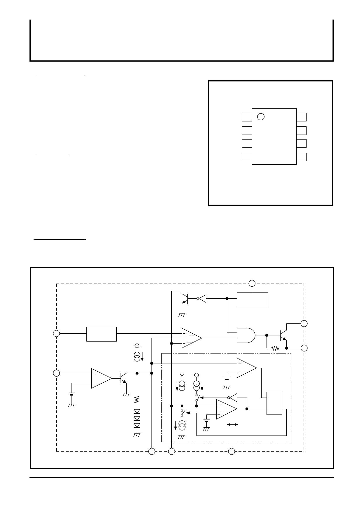
BLOCK DIAGRAM
COSC 4
IN 7
OSC
VCC
OP Amp
1.25V
VCC
8
UVLO
VTH : 2.3V
PWM Comp
Collector
1 output
1.25V
VCC
Short protection
circuit
2 Emitter
output
1.86V
R
SQ
1.15V 0.3V
65
FB DTC
(1/8)
3
GND
1 page 
MITSUBISHI SEMICONDUCTORS <Standard Linear ICs>
M62212P/FP/GP
GENERAL PURPOSE DC-DC CONVERTER
2. FUNCTION DESCRIPION
1) Soft Start (The peripheral circuit is shown in Fig.1)
When the power is turned ON, input terminal IN is at 0V level. Therefore, the FB
terminal is fixed to High level. The DTC terminal goes up gradually starting from 0V
due to the internal charge current and the external CDTC.
When the level of DTC terminal reaches the lower limit of the triangular wave of the
oscillator, PWM comparator and the output circuit go into operation causing the output
voltage, "Vo" of the DC-DC converter to rise. The charge current is designed to be
approximately 45µA.
FB
OSC
DTC
1.0V
0.45V
OFF
External Tr collector
ON
Fig.2
2) DTC
The dead time control is set by installing a resistor between the DTC terminal and GND.
However, the DTC terminal serves as the short protection circuit also. Therefore, its set up
depends on whether the short protection circuit is used and not.
(When the short protection circuit is used)
At this time, the charge current for DTC is approximately 10µA . Therefore, RDTC should
be set to 40KΩ ~ 110KΩ.
(When the short protection circuit is not used)
At this time, the charge current for DTC is approximately 45µA. Therefore, RDTC is set to
12KΩÅ`25KΩ.
(5/8)
5 Page | ||
| Páginas | Total 8 Páginas | |
| PDF Descargar | [ Datasheet M62212GP.PDF ] | |
Hoja de datos destacado
| Número de pieza | Descripción | Fabricantes |
| M62212GP | GENERAL PURPOSE DC-DC CONVERTER | Mitsubishi |
| Número de pieza | Descripción | Fabricantes |
| SLA6805M | High Voltage 3 phase Motor Driver IC. |
Sanken |
| SDC1742 | 12- and 14-Bit Hybrid Synchro / Resolver-to-Digital Converters. |
Analog Devices |
|
DataSheet.es es una pagina web que funciona como un repositorio de manuales o hoja de datos de muchos de los productos más populares, |
| DataSheet.es | 2020 | Privacy Policy | Contacto | Buscar |