|
|
|
PDF RHR1K160D Data sheet ( Hoja de datos )
| Número de pieza | RHR1K160D | |
| Descripción | 1A/ 600V Hyperfast Dual Diode | |
| Fabricantes | Intersil Corporation | |
| Logotipo | ||
Hay una vista previa y un enlace de descarga de RHR1K160D (archivo pdf) en la parte inferior de esta página. Total 9 Páginas | ||
|
No Preview Available !
Data Sheet
RHR1K160D
January 2000
File Number 4788
[ /Title
(RHR1
K160D
)
/Sub-
ject
(1A,
600V
Hyper-
fast
Dual
Diode)
/Autho
r ()
/Key-
words
(Inter-
sil
Corpo-
ration,
semi-
con-
ductor,
Ava-
lanche
Energy
Rated,
Switch
ing
Power
Sup-
plies,
Power
Switch
ing
Cir-
cuits,
Rectifi-
ers,
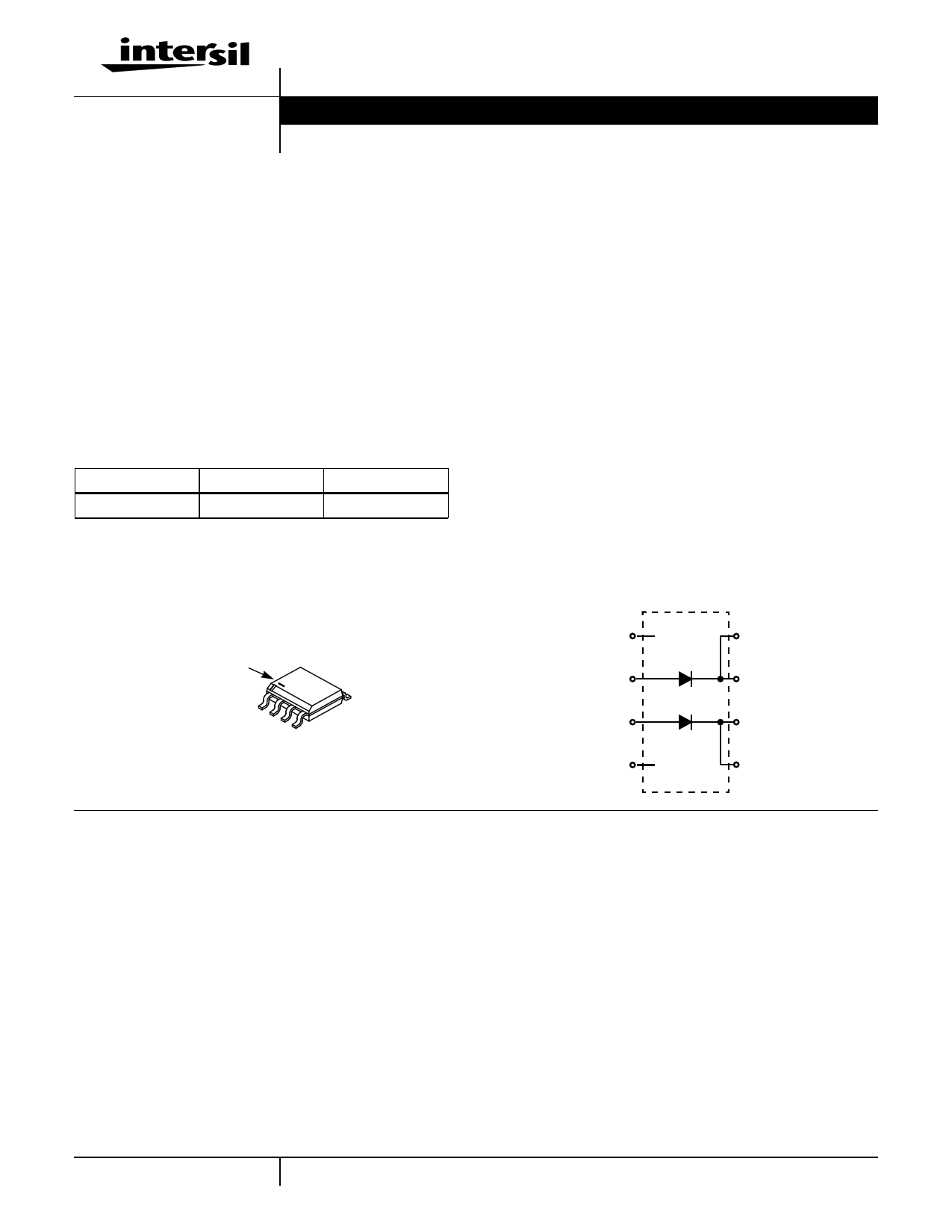
1A, 600V Hyperfast Dual Diode
The RHR1K160D is a hyperfast dual diode with soft recovery
characteristics (trr < 25ns). It has about half the recovery
time of ultrafast diodes and is silicon nitride passivated ion-
implanted epitaxial planar construction.
This device is intended for use as freewheeling/clamping
diodes and rectifiers in a variety of switching power supplies
and other power switching applications. Its low stored charge
and hyperfast soft recovery minimize ringing and electrical
noise in many power switching circuits reducing power loss
in the switching transistors.
Formerly developmental type TA49185.
Ordering Information
PART NUMBER
PACKAGE
BRAND
RHR1K160D
MS-012AA
RHR1K160D
NOTE: When ordering, use the entire part number. For ordering in
tape and reel, add the suffix 96 to the part number, i.e.,
RHR1K160D96.
Packaging
JEDEC MS-012AA
BRANDING DASH
1
23 4
5
Features
• Hyperfast with Soft Recovery . . . . . . . . . . . . . . . . . . <25ns
• Operating Temperature. . . . . . . . . . . . . . . . . . . . . . .150oC
• Reverse Voltage . . . . . . . . . . . . . . . . . . . . . . . . . . . . .600V
• Thermal Impedance SPICE® Model
• Thermal Impedance SABER© Model
• Avalanche Energy Rated
• Planar Construction
• Related Literature
- TB334, “Guidelines for Soldering Surface Mount
Components to PC Boards”
Applications
• Switching Power Supplies
• Power Switching Circuits
• General Purpose
Symbol
NC (1)
ANODE 1 (2)
CATHODE 1 (8)
CATHODE 1 (7)
ANODE 2 (3)
NC (4)
CATHODE 2 (6)
CATHODE 2 (5)
Absolute Maximum Ratings (Per Leg) TA = 25oC, Unless Otherwise Specified
Peak Repetitive Reverse Voltage . . . . . . . . . . . . . . . . . . . . . . . . . . . . . . . . . . . . . . . . . . . VRRM
Working Peak Reverse Voltage . . . . . . . . . . . . . . . . . . . . . . . . . . . . . . . . . . . . . . . . . . . .VRWM
DC Blocking Voltage . . . . . . . . . . . . . . . . . . . . . . . . . . . . . . . . . . . . . . . . . . . . . . . . . . . . . . VR
Average Rectified Forward Current . . . . . . . . . . . . . . . . . . . . . . . . . . . . . . . . . . . . . . . . . IF(AV)
TA = 65oC
Repetitive Peak Surge Current . . . . . . . . . . . . . . . . . . . . . . . . . . . . . . . . . . . . . . . . . . . . . IFRM
Square Wave, 20kHz
Nonrepetitive Peak Surge Current . . . . . . . . . . . . . . . . . . . . . . . . . . . . . . . . . . . . . . . . . . . IFSM
Halfwave, 1 phase, 60Hz
Maximum Power Dissipation (Note 1) . . . . . . . . . . . . . . . . . . . . . . . . . . . . . . . . . . . . . . . . . PD
Avalanche Energy (See Figures 11 and 12) . . . . . . . . . . . . . . . . . . . . . . . . . . . . . . . . . . .EAVL
Operating and Storage Temperature . . . . . . . . . . . . . . . . . . . . . . . . . . . . . . . . . . . . . TSTG,TJ
Maximum Temperature for Soldering
Leads at 0.063in (1.6mm) from Case for 10s. . . . . . . . . . . . . . . . . . . . . . . . . . . . . . . . . . TL
Package Body for 10s, See Techbrief 334 . . . . . . . . . . . . . . . . . . . . . . . . . . . . . . . . . . .Tpkg
RHR1K160D
600
600
600
1
2
10
2.5
5
-55 to 150
300
260
UNITS
V
V
V
A
A
A
W
mJ
oC
oC
oC
1 1-888-INTERSIL or 321-724-7143 | Copyright © Intersil Corporation 2000
SABER is a Copyright of Analogy, Inc.
1 page 
RHR1K160D
Thermal Resistance vs Mounting Pad Area
The maximum rated junction temperature, TJM, and the
thermal resistance of the heat dissipating path determines
the maximum allowable device power dissipation, PDM, in an
application. Therefore the application’s ambient temperature,
TA (oC), and thermal resistance RθJA (oC/W) must be
reviewed to ensure that TJM is never exceeded. Equation 1
mathematically represents the relationship and serves as
the basis for establishing the rating of the part.
PDM = -(--T----J-Z--M--θ----J–---A-T----A----)
(EQ. 1)
In using surface mount devices such as the SOP-8 package,
the environment in which it is applied will have a significant
influence on the part’s current and maximum power
dissipation ratings. Precise determination of PDM is complex
and influenced by many factors:
1. Mounting pad area onto which the device is attached and
whether there is copper on one side or both sides of the
board.
2. The number of copper layers and the thickness of the
board.
3. The use of external heat sinks.
4. The use of thermal vias.
5. Air flow and board orientation.
6. For non steady state applications, the pulse width, the
duty cycle and the transient thermal response of the part,
the board and the environment they are in.
Intersil provides thermal information to assist the designer’s
preliminary application evaluation. Figure 13 defines the
RθJA for the device as a function of the top copper
(component side) area. This is for a horizontally positioned
FR-4 board with 2 oz. copper after 1000 seconds of steady
state power with no air flow. This graph provides the
necessary information for calculation of the steady state
junction temperature or power dissipation. Pulse
applications can be evaluated using the Intersil device
SPICE thermal model or manually utilizing the normalized
maximum transient thermal impedance curve.
350
RθJA = 110.2 - 25.24 x ln (AREA)
300
239oC/W - 0.006in2
250
201oC/W - 0.027in2
200
150
100
Rθβ = 43.81 - 22.66 x ln (AREA)
50
0.001
0.01
AREA, TOP COPPER AREA (in2)
0.1
FIGURE 13. THERMAL RESISTANCE vs MOUNTING PAD AREA
Displayed on the curve are RθJA values listed in the
Electrical Specifications table. These points were chosen to
depict the compromise between the copper board area, the
thermal resistance and ultimately the power dissipation,
PDM. Thermal resistances corresponding to other
component side copper areas can be obtained from Figure
13 or by calculation using Equation 2. The area, in square
inches is the top copper board area, the thermal resistance
and ultimately the power dissipation, PDM.
RθJA = 110.18 – 25.24 × ln (Area)
(EQ. 2)
While Equation 2 describes the thermal resistance of a
single die, the dual die SOP-8 package introduces an
additional thermal component, thermal coupling resistance,
Rθβ. Equation 3 describes Rθβ as a function of the top
copper mounting pad area.
Rθβ = 43.81 – 22.66 × ln (Area)
(EQ. 3)
The thermal coupling resistance vs. copper area is also
graphically depicted in Figure 13. It is important to note the
thermal resistance (RθJA) and thermal coupling resistance
(Rθβ) are equivalent for both die. For example at 0.1 square
inches of copper:
RθJA1 = RθJA2 = 168oC/W
Rθβ1 = Rθβ2 = 96oC/W
TJ1 and TJ2 define the junction temperature of the
respective die. Similarly, P1 and P2 define the power
dissipated in each die. The steady state junction
temperature can be calculated using Equation 4 for die 1
and Equation 5 for die 2.
Example: Use Equation 4 to calculate TJ1 and Equation 5 to
calculate TJ2 with the following conditions. Die 2 is
dissipating 0.5W; die 1 is dissipating 0W; the ambient
temperature is 60oC; the package is mounted to a top
copper area of 0.1 square inches per die.
5
5 Page | ||
| Páginas | Total 9 Páginas | |
| PDF Descargar | [ Datasheet RHR1K160D.PDF ] | |
Hoja de datos destacado
| Número de pieza | Descripción | Fabricantes |
| RHR1K160 | 1A/ 600V Hyperfast Diode | Intersil Corporation |
| RHR1K160D | 1A/ 600V Hyperfast Dual Diode | Intersil Corporation |
| Número de pieza | Descripción | Fabricantes |
| SLA6805M | High Voltage 3 phase Motor Driver IC. |
Sanken |
| SDC1742 | 12- and 14-Bit Hybrid Synchro / Resolver-to-Digital Converters. |
Analog Devices |
|
DataSheet.es es una pagina web que funciona como un repositorio de manuales o hoja de datos de muchos de los productos más populares, |
| DataSheet.es | 2020 | Privacy Policy | Contacto | Buscar |