|
|
|
PDF IRADK10 Data sheet ( Hoja de datos )
| Número de pieza | IRADK10 | |
| Descripción | 3-phase 115-230V 0.5HP Variable speed Motor Drive control for Appliances and light Industrial Applications. | |
| Fabricantes | International Rectifier | |
| Logotipo | ||
Hay una vista previa y un enlace de descarga de IRADK10 (archivo pdf) en la parte inferior de esta página. Total 11 Páginas | ||
|
No Preview Available !
IRADK10
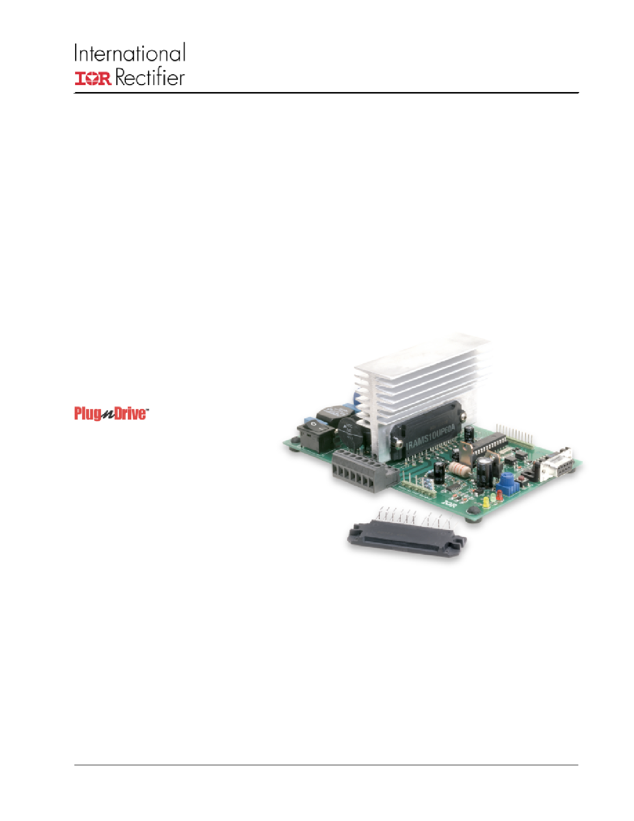
IRADK10 Motor Drive
Reference Design Kit
Demo kit Board Features
• 115/230VAC input,
• 400W, 3 Phase,variable voltage output.
• NTC thermistor inrush current limiter.
• Micro controller 8-Bit with A/D converter.
• Constant volt-seconds control.
• Opto-isolated RS-232 serial link interface to
the Graphic User Interface software.
• Fault protection for over current and over
temperature.
• Integral aux. power +15V and +5V.
• AC input EMI filter and on/off switch.
3-phase 115-230V 0.5HP
Variable speed Motor Drive
control for Appliances and
light Industrial Applications.
Power Module
• 600V NPT IGBT technology.
• Current rating 5A @ Tc=100°C.
• Monolithic IC Driver.
• Cross-conduction prevention logic.
• Optimized gate drive for reduced EMI.
• IMS substrate ground plane provides
EMI shielding.
• Fully isolated screw mount package.
Graphic User Interface Control Software
• Displays DC-link current and power module
and heat sink temperatures.
• Displays Driver status.
• GUI user settable parameters:
• Motor operating frequency.
• IGBT conduction dead time.
• Motor acceleration.
• PWM frequency.
• IGBT temperature limit.
Figure 1 IRADK10 Reference Design Kit
www.irf.com
1
1 page 
IRADK10
PWM phase command signals
Connecting the inverter to the motor.
This carries the signals as shown below. Note that these
signals are referenced to the negative DC power rail which
is not at ground potential. Beware of electric shock haz-
ard and do not connect any grounded test equipment
such as an oscilloscope to these test pins.
Pin 1: Phase A upper switch ON command, inverted
Pin 2: Phase B upper switch ON command, inverted
Pin 3: Phase C upper switch ON command, inverted
Pin 4: Phase A lower switch ON command, inverted
Pin 5: Phase B lower switch ON command, inverted
Pin 6: Phase C lower switch ON command, inverted
Pin 7: ITRIP signal
Pin 8: SP1 spare digital input
Pin 9: SP2 spare digital input
Pin 10: GROUND (0V) referred to - DC bus
Pin 11: Spare analog input referred to -DC bus rail
Pin 12: +5V auxiliary power supply referred to - DC bus
rail
High voltage signals J2
This connector J2 carries the motor drive voltages and the
DC bus voltage. Use the same cautions as referenced
above for the PWM phase command signals.
Pin 1: Phase A motor voltage
Pin 3: Phase B motor voltage
Pin 5: Phase C motor voltage
Pin 7: MINUS DC bus rail
Pin 10: PLUS DC bus rail
Power Connector J1
Use a 3-phase 115V Y connected or 220V delta connected
induction motor rated at ½ HP or less.
Provide a 3 wire, 2A minimum rated cable for the motor con-
nection, and a 3 wire 2A minimum rated cable for the AC
mains connections. Make sure you also attach the ground
connection. The motor phase connections can be connected
in any sequence, only the rotation direction will be affected.
Make all the necessary connections, including the serial link
with the PC before applying AC power.
Operating the motor via the GUI tool.
After connecting all the cables and selecting the desired
settings in the GUI, apply the AC power via S2 in position 1.
After a few seconds, provided the main voltage is within tol-
erances, the yellow LED diode will flash denoting the pres-
ence of the DC-bus voltage.
Start the GUI tool. The first screen will prompt you for the
COM port used for PC to DEMO board communication as
is showed in the figure 4. Select either COM1 or COM2 for
this purpose.
Power connector provides the input AC power and the
motor connections.
Pin 1: Input AC voltage (115V or 220V) phase
Pin 2: Input AC voltage (115V or 220V) neutral
Pin 3: Ground connection ( has to be connected to
reduce the EMI noise)
Pin 4: Ground connection
Pin 5: Phase C motor connection
Pin 6: Phase B motor connection
Pin 7: Phase A motor connection
110V/220V selector switch S3
S3 is the selector switch to set the correct rectifier configu-
ration to the AC input.. Prior to connecting the system to the
AC input, carefully check the position of S3. Operate the
switch only when the AC is OFF. The drive will be dam-
aged and the user could be injured by ignoring this warning.
Figure 4. GUI serial connection selections
This will lead you to the next screen. Observe at the top-left
a white field with the “DRIVE STATUS” label. Pressing the
“REFRESH SCREEN” button will read the drive status (ON,
OFF, eventual SC, OV, UV, I2T, and heat sink over tempera-
ture) and print a message in the top-left white field. Below
the “DRIVE STATUS” field, another white field is observed
with the caption “DC-link current average value over 5 sec-
onds”. Pressing the “REFRESH SCREEN” button will read
the drive DC-link current averaged over 5 seconds and dis-
play the value in mA units. Further below, in the same far left
column, another white field is observed with the caption “Heat
sink temperature”. Pressing the “REFRESH SCREEN” but-
ton will read the drive heat sink temperature and display the
value in degrees Centigrade.
www.irf.com
5
5 Page 
IRADK10
The information presented in this paper is believed to be accurate and reliable. However, International Rectifier can assume no responsi-
bility for its use nor any infringement of patents or other rights of third parties which may result from its use. No license is granted by
implication or other use under any patent or patent rights of International Recitifier. No patent liability shall be incurred for use of the circuits
or devices described herein.
Printed in U.S.A. 11/08
© 2002 International Rectifier rev. 1
WORLD HEADQUARTERS: 233 KANSAS ST., EL SEGUNDO, CA 90245, USA
N.A.
N.E. US
+1 203 355 1228
S. US
+1 919 844 5499
S.W. US
+1 949 838 0161
N.W. US
+1 303 469 6303
EUROPE
ITALY
+39 011 451 0111
GERMANY
+49 6102 884 400
GREAT BRITAIN
+44 20 8645 8000
TECHNICAL ASSISTANCE CENTER : N.A. +1 310 252 7105
EUROPE: +44 20 8645 8015
ASIA: + 65 6838 4632
HTTP://TAC.IRF.COM
www.irf.com
11
11 Page | ||
| Páginas | Total 11 Páginas | |
| PDF Descargar | [ Datasheet IRADK10.PDF ] | |
Hoja de datos destacado
| Número de pieza | Descripción | Fabricantes |
| IRADK10 | 3-phase 115-230V 0.5HP Variable speed Motor Drive control for Appliances and light Industrial Applications. | International Rectifier |
| Número de pieza | Descripción | Fabricantes |
| SLA6805M | High Voltage 3 phase Motor Driver IC. |
Sanken |
| SDC1742 | 12- and 14-Bit Hybrid Synchro / Resolver-to-Digital Converters. |
Analog Devices |
|
DataSheet.es es una pagina web que funciona como un repositorio de manuales o hoja de datos de muchos de los productos más populares, |
| DataSheet.es | 2020 | Privacy Policy | Contacto | Buscar |