|
|
|
PDF IR2113S Data sheet ( Hoja de datos )
| Número de pieza | IR2113S | |
| Descripción | HIGH AND LOW SIDE DRIVER | |
| Fabricantes | International Rectifier | |
| Logotipo | ||
Hay una vista previa y un enlace de descarga de IR2113S (archivo pdf) en la parte inferior de esta página. Total 16 Páginas | ||
|
No Preview Available !
Data Sheet No. PD60147 Rev.T
IR2110(S)/IR2113(S) &(PbF)
HIGH AND LOW SIDE DRIVER
Features
• Floating channel designed for bootstrap operation
Fully operational to +500V or +600V
Tolerant to negative transient voltage
dV/dt immune
• Gate drive supply range from 10 to 20V
• Undervoltage lockout for both channels
• 3.3V logic compatible
Separate logic supply range from 3.3V to 20V
Logic and power ground ±5V offset
• CMOS Schmitt-triggered inputs with pull-down
• Cycle by cycle edge-triggered shutdown logic
• Matched propagation delay for both channels
• Outputs in phase with inputs
• Also available LEAD-FREE
Product Summary
VOFFSET (IR2110) 500V max.
(IR2113) 600V max.
IO+/-
2A / 2A
VOUT
10 - 20V
ton/off (typ.)
120 & 94 ns
Delay Matching (IR2110) 10 ns max.
(IR2113) 20ns max.
Packages
Description
The IR2110/IR2113 are high voltage, high speed power MOSFET and
IGBT drivers with independent high and low side referenced output chan-
nels. Proprietary HVIC and latch immune CMOS technologies enable
ruggedized monolithic construction. Logic inputs are compatible with
standard CMOS or LSTTL output, down to 3.3V logic. The output
drivers feature a high pulse current buffer stage designed for minimum
14-Lead PDIP
IR2110/IR2113
16-Lead SOIC
IR2110S/IR2113S
(Also available
LEAD-FREE (PbF))
driver cross-conduction. Propagation delays are matched to simplify use in high frequency applications. The
floating channel can be used to drive an N-channel power MOSFET or IGBT in the high side configuration which
operates up to 500 or 600 volts.
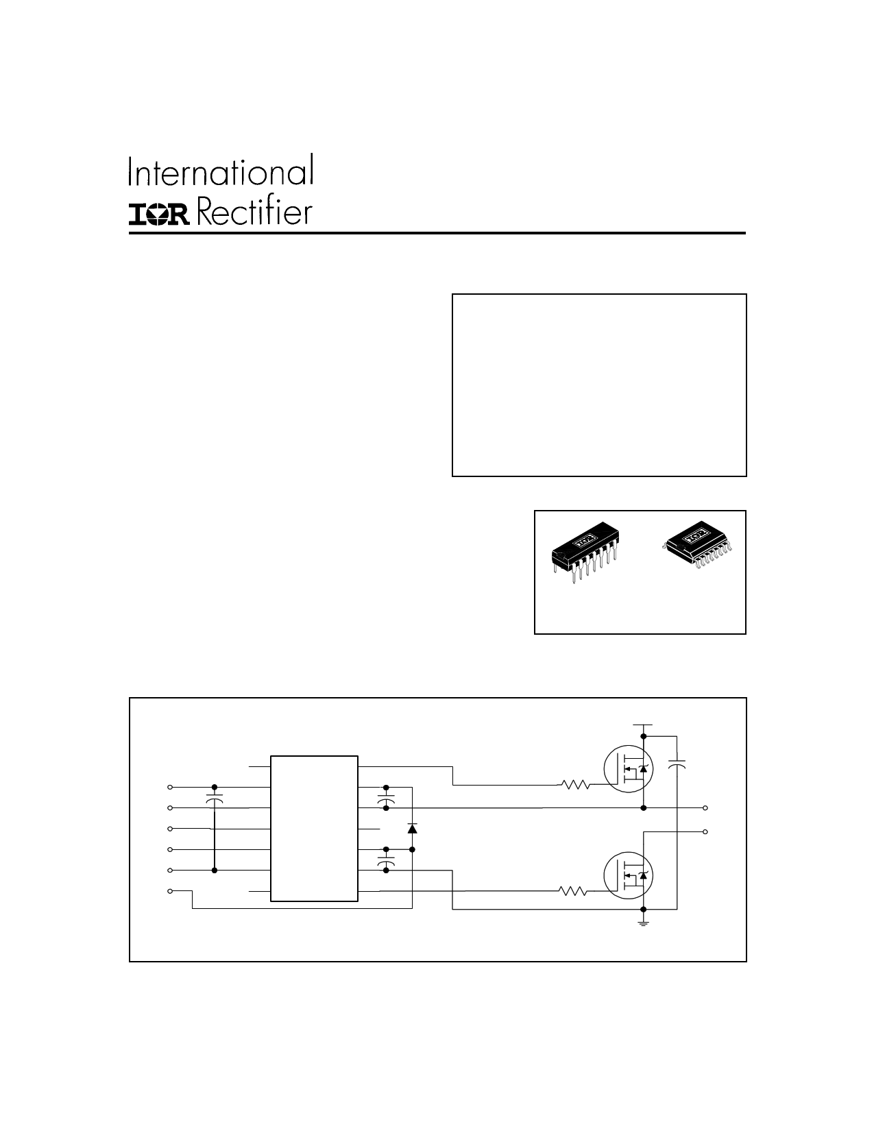
Typical Connection
up to 500V or 600V
HO
VDD
VDD
VB
HIN HIN VS
SD SD
LIN LIN VCC
VSS VSS COM
VCC LO
(Refer to Lead Assignments for correct pin configuration). This/These diagram(s) show electrical
connections only. Please refer to our Application Notes and DesignTips for proper circuit board layout.
www.irf.com
TO
LOAD
1
1 page 
IR2110(S)/IR2113(S) &(PbF)
Vcc =15V
HV = 10 to 500V/600V
10 0.1
µF µF
9
10
11
12
13
10KF6
36
5
7
0.1
µF
200
µH
HO
1
OUTPUT 10KF6
MONITOR
2
IRF820
+
100µF
10KF6
dVS >50 V/ns
dt
Figure 1. Input/Output Timing Diagram
Figure 2. Floating Supply Voltage Transient Test Circuit
Vcc =15V
10
µF
HIN
SD
LIN
0.1
µF
9
10
11
12
13
3
2
6
5
7
1
0.1
µF
CL
HO
LO
CL
VB
10
µF
+
15V
- VS
(0 to 500V/600V)
10
µF
HIN
LIN
ton
HO
LO
50%
50%
tr
90%
toff tf
90%
10%
10%
Figure 3. Switching Time Test Circuit
Figure 4. Switching Time Waveform Definition
50%
SD
tsd
HO 90%
LO
Figure 5. Shutdown Waveform Definitions
www.irf.com
HIN 50%
LIN
50%
LO HO
10%
MT MT
90%
LO HO
Figure 6. Delay Matching Waveform Definitions
5
5 Page 
IR2110(S)/IR2113(S) &(PbF)
60
50
40
30
20
10
0
0 2 4 6 8 10 12 14 16 18 20
VDD Logic Supply Voltage (V)
Figure 20B. Logic “1” Input Current vs. VDD Voltage
5
4
3
2
1
0
0 2 4 6 8 10 12 14 16 18 20
VDD Logic Supply Voltage (V)
Figure 21B. Logic “0” Input Current vs. VDD Voltage
5.00
4.00
3.00
2.00
Max.
1.00
0.00
-50
-25
0 25 50 75
Temperature (°C)
100 125
Figure 21A. Logic “0” Input Current vs. Temperature
11.0
10.0
Max.
9.0
Typ.
8.0
Min.
7.0
6.0
-50
-25
0 25 50 75
Temperature (°C)
100 125
Figure 22. VBS Undervoltage (+) vs. Temperature
11.0
10.0
Max.
9.0
Typ.
8.0
7.0 Min.
6.0
-50
-25
0 25 50 75
Temperature (°C)
100 125
Figure 23. VBS Undervoltage (-) vs. Temperature
11.0
10.0
Max.
9.0
Typ.
8.0
Min.
7.0
6.0
-50
-25
0 25 50 75
Temperature (°C)
100 125
Figure 24. VCC Undervoltage (+) vs. Temperature
www.irf.com
11
11 Page | ||
| Páginas | Total 16 Páginas | |
| PDF Descargar | [ Datasheet IR2113S.PDF ] | |
Hoja de datos destacado
| Número de pieza | Descripción | Fabricantes |
| IR2113 | HIGH AND LOW SIDE DRIVER | International Rectifier |
| IR2113C | (IR2110C / IR2113C) High and Low Side Driver in Die Wafer Form | International Rectifier |
| IR2113PBF | HIGH AND LOW SIDE DRIVER | International Rectifier |
| IR2113S | HIGH AND LOW SIDE DRIVER | International Rectifier |
| Número de pieza | Descripción | Fabricantes |
| SLA6805M | High Voltage 3 phase Motor Driver IC. |
Sanken |
| SDC1742 | 12- and 14-Bit Hybrid Synchro / Resolver-to-Digital Converters. |
Analog Devices |
|
DataSheet.es es una pagina web que funciona como un repositorio de manuales o hoja de datos de muchos de los productos más populares, |
| DataSheet.es | 2020 | Privacy Policy | Contacto | Buscar |