|
|
|
PDF DAC488HR Data sheet ( Hoja de datos )
| Número de pieza | DAC488HR | |
| Descripción | 16-bit D/A Converter with Digital I/O & IEEE 488 | |
| Fabricantes | ETC | |
| Logotipo | ||
Hay una vista previa y un enlace de descarga de DAC488HR (archivo pdf) en la parte inferior de esta página. Total 4 Páginas | ||
|
No Preview Available !
®
the smart approach to instrumentation™
DAC488HR™
16-bit D/A Converter with Digital I/O & IEEE 488
Features
• Two or four isolated 16-bit outputs
• 100-kHz/channel update rate
• 480 Ksamples/channel max buffer
• ±1, ±2, ±5, & ±10 VFS programmable
unipolar & bi-polar output ranges
• One-shot, step, burst, waveform, &
continuous output modes
• GET, external TTL, IEEE command,
& time event trigger sources
• ASCII, binary, integer decimal, & hexa-
decimal data formats
• Standard sine, square, & triangle
waveform generation
• 500 VDC channel-to-channel isolation
• Eight digital inputs & eight digital
outputs
• 100 mA high-current outputs
• LabVIEW® drivers
The DAC488HR™ is an IEEE 488 program-
mable 16-bit D/A converter. It can be
configured with either two or four output
channels, which are optically isolated from
each other and from IEEE 488 common
by up to 500 VDC. Each channel is inde-
pendently programmable for 1, 2, 5, or 10
VFS unipolar or bipolar output, specified
as either bits or volts in ASCII, integer,
hexadecimal, or binary format. Multiple
output modes, multiple clock and trigger
sources, and buffer management enable
the DAC488HR to function as a precision
voltage source, a function generator, or
an arbitrary waveform generator.
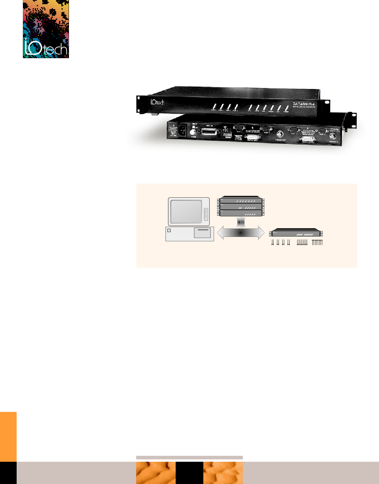
The versatile DAC488HR functions as a voltage source, function generator, and an arbitrary
waveform generator
IEEE 488
controller
Up to 13 IEEE 488 devices
SCSI488/S
DAC488HR/2
Filter488
IEEE
DAC488HR
DAC488HR
+- +- +- +-
CH1 CH2 CH3 CH4
8 digital
outputs
2- or 4-channel 16-bit,
isolated 100-kHz
analog outputs
8 digital
inputs
Trigger Modes
The DAC488HR’s five trigger modes sup-
port a wide variety of applications.
Burst Mode. Functionally identical to step
mode, except that waveforms rather than
single values are output.
Waveforms captured by IOtech’s 16-bit,
100-kHz ADC488A series (see p. 243) digi-
tizers can be edited and transferred to the
DAC488HR for output. The ADC488A™
series and DAC488HR in combination
form a powerful waveform I/O system.
Typical applications include transducer
simulation, disk drive testing, vibration
analysis, and materials testing.
BusControlMode. Eachportisprogrammed
to output a specified value under direct
control from the IEEE 488 bus. This mode is
useful for maintaining an initial value until
a specified condition occurs.
Step Mode. When a specified trigger is
detected, a value is output from the
buffer, and the DAC488HR is automati-
cally re-armed until the specified buffer
count is reached. The last specified buffer
value is held as the output.
Waveform Mode. Based on recognition
of a trigger, the waveform buffer is output
for a specified number of cycles.
Continuous Mode. Data is continuously
input from the IEEE 488 bus and output to
an analog channel at rates up to 200 Kbytes/s
upon the detection of a specified trigger.
This mode is ideally suited for audio, speech,
and other applications that require long
duration waveforms.
tel: 440-439-4091 fax: 440-439-4093
QUICK FIND
248
[email protected] www.iotech.com
1 page | ||
| Páginas | Total 4 Páginas | |
| PDF Descargar | [ Datasheet DAC488HR.PDF ] | |
Hoja de datos destacado
| Número de pieza | Descripción | Fabricantes |
| DAC488HR | 16-bit D/A Converter with Digital I/O & IEEE 488 | ETC |
| Número de pieza | Descripción | Fabricantes |
| SLA6805M | High Voltage 3 phase Motor Driver IC. |
Sanken |
| SDC1742 | 12- and 14-Bit Hybrid Synchro / Resolver-to-Digital Converters. |
Analog Devices |
|
DataSheet.es es una pagina web que funciona como un repositorio de manuales o hoja de datos de muchos de los productos más populares, |
| DataSheet.es | 2020 | Privacy Policy | Contacto | Buscar |