|
|
|
PDF HSSR711X Data sheet ( Hoja de datos )
| Número de pieza | HSSR711X | |
| Descripción | 90 V/1.0 W/ Hermetically Sealed/ Power MOSFET Optocoupler | |
| Fabricantes | Agilent(Hewlett-Packard) | |
| Logotipo | ||
Hay una vista previa y un enlace de descarga de HSSR711X (archivo pdf) en la parte inferior de esta página. Total 13 Páginas | ||
|
No Preview Available !
H
400 V/10 Ohm,
General Purpose, 1 Form A,
Solid State Relay
Technical Data
HSSR-8400
Features
• Compact Solid-State
Bidirectional Switch
• Normally-Off Single-Pole
Relay Function (1 Form-A)
• 400 V Output Withstand
Voltage in Both Polarities at
25°C
• 150/300 mA Current Ratings
(See Schematic for
Connection A & B)
• Low Input Current; CMOS
Compatibility
• Very Low On-Resistance: 6 Ω
Typical at 25°C
• ac/dc Signal & Power
Switching
• Input-to-Output Momentary
Withstand Insulation
Voltage: 2500 Vac, 1 Minute
• 16-kV ESD Immunity: MIL-
STD-883, Method 3015
• CSA Approved
• UL 508 Recognized
Applications
• Modems
• Telecommunication
Switching Equipment
• Telecommunication Test
Instruments
• Reed Relay Replacement
• 110/220 Vac Load Driver
• Industrial Relay Coil Driver
Description
The HSSR-8400 consists of a
high-voltage circuit, optically
coupled with a Light-Emitting
Diode (LED). This device is a
solid-state replacement for single-
pole, normally-open (1 Form A)
electromechanical relays used for
general purpose switching of
signals and low-power ac/dc
loads. The relay turns on (contact
closes) with a minimum input
current, IF, of 5 mA through the
input LED. The relay turns off
(contact opens) with an input
voltage, VF, of 0.8 V or less. The
detector contains a high speed
photosensitive FET driver circuit
and two high voltage MOSFETs.
This relay’s logic-level input con–
trol and very low typical output
on-resistance of 6 Ω make it
suitable for switching of audio
frequency signals in telecom
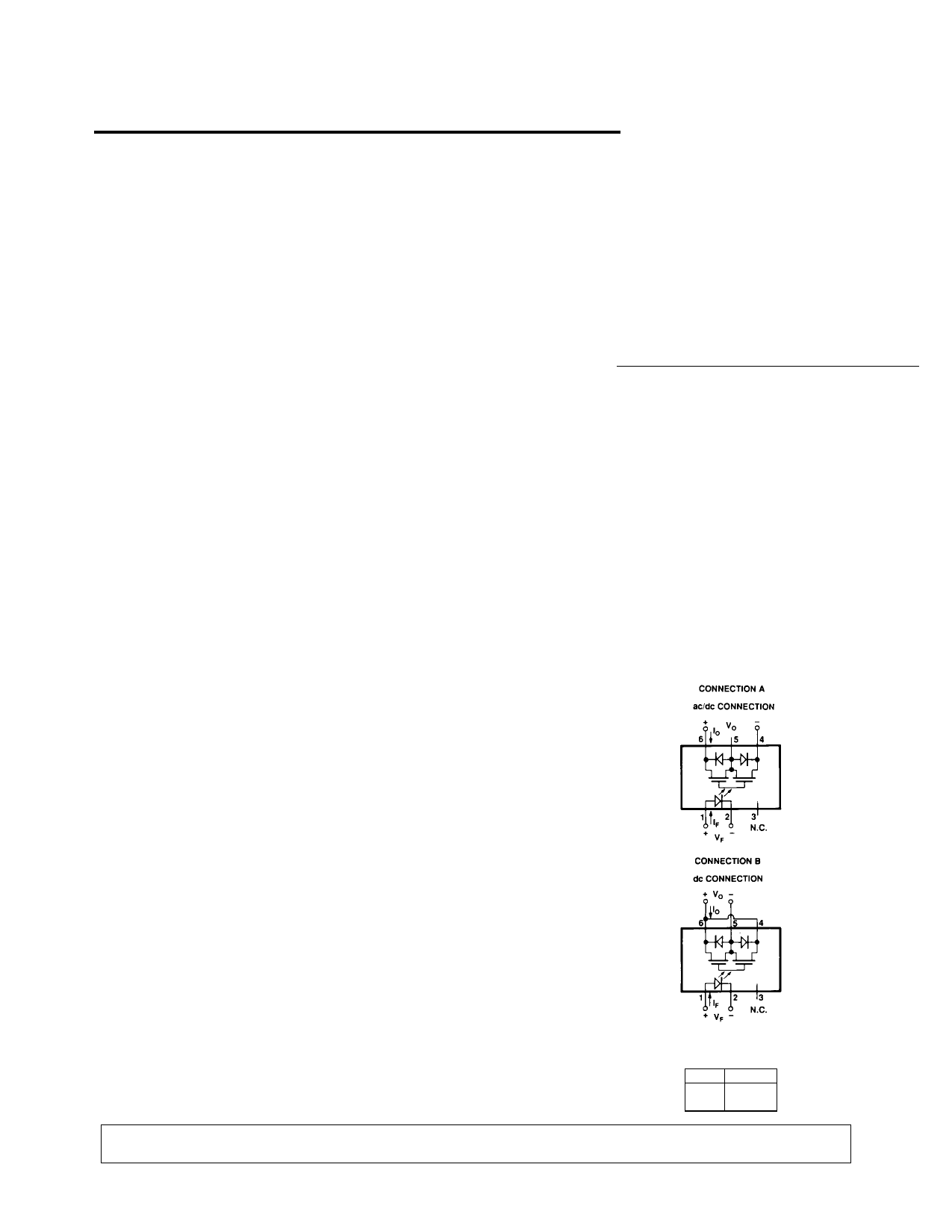
applications. Connection A, as
shown in the schematic, allows
the relay to switch either ac or dc
loads. In this configuration, the
150 mA output current rating
allows it to switch small loads
that are driven from 110 Vac and
220 Vac power lines. Connection
B, with the polarity and pin
configuration as indicated in the
schematic, allows the relay to
switch dc loads only. The
advantage of Connection B is that
the on-resistance is significantly
reduced and the output current
capability increases by a factor of
two.
The electrical and switching
characteristics of the HSSR-8400
are specified from -40°C to
+85°C.
Functional Diagram
TRUTH TABLE
(POSITIVE LOGIC)
LED OUTPUT
ON L
OFF
H
CAUTION: It is advised that normal static precautions be taken in handling and assembly of this component to
prevent damage and/or degradation which may be induced by ESD.
5965-3573E
1-465
1 page 
Regulatory Information
The HSSR-8400 has been
approved by the following
organizations:
UL
Recognized under UL 508,
Component Recognition
Program, Industrial Control
Switches, File E142465.
CSA
Approved under CAN/CSA-C22.2
No. 14-95, Industrial Control
Equipment, File LR 87683.
Insulation and Safety Related Specifications
Parameter
Symbol Value Units
Conditions
Min. External Air Gap
(External Clearance)
L(IO1) 7.0 mm Measured from input terminals to output
terminals, shortest distance through air
Min. External Tracking Path
(External Creepage)
L(IO2) 8.5 mm Measured from input terminals to output
terminals, shortest distance path along body
Min. Internal Plastic Gap
(Internal Clearance)
0.5 mm Through insulation distance, conductor to
conductor, usually the direct distance
between the photoemitter and photodetector
inside the optocoupler cavity
Tracking Resistance
(Comparative Tracking Index)
CTI
200 volts DIN IEC 112/VDE 0303 PART 1
Isolation Group
IIIa Material Group (DIN VDE 0110, 1/89, Table 1)
Option 300 – surface mount classification is Class A in accordance with CECC 00802.
Absolute Maximum Ratings
Storage Temperature ................................................... -55°C to+125°C
Operating Temperature - TA .......................................... -40°C to +85°C
Case Temperature - TC .......................................................... +105°C[1]
Lead Solder Temperature .... 260°C for 10 S (1.6 mm below seating plane)
Average Input Current - IF ............................................................ 20 mA
Repetitive Peak Input Current - IF ............................................... 40 mA
(Pulse Width ≤ 1 ms; duty cycle ≤ 50%)
Transient Peak Input Current - IF ............................................... 100 mA
(Pulse Width ≤ 200 µs; duty cycle ≤ 1%)
Reverse Input Voltage - VR ................................................................ 3 V
Input Power Dissipation .............................................................. 40 mW
Output Voltage (TA = 25°C)
Connection A - VO ..................................................... - 400 to +400 V
Connection B - VO ........................................................... 0 to +400 V
Average Output Current - Figure 3 (TA = 25°C, TC ≤ 70°C)
Connection A - IO ..................................................................... 0.15 A
Connection B - IO ....................................................................... 0.3 A
Single Shot Peak Output Current
(100 ms pulse width, TA = 25°C, IF = 10 mA)
Connection A - IO ...................................................................... 1.0 A
Connection B - IO ...................................................................... 2.0 A
Output Power Dissipation ..................................................... 750 mW[2]
Infrared and Vapor Phase Reflow Temperature
(Option #300) ......................................... See Fig. 1, Thermal Profile
Thermal Resistance
Typical Output MOSFET Junction
to Case – θJC = 55°C/W
Demonstrated ESD
Performance
Human Body Model: MIL-STD-
883 Method 3015.7 - 16 kV
Machine Model: EIAJ 1988.3.28
Version 2), Test Method 20,
Condition C – 1200 V
1-469
5 Page 
Figure 17. Input-Output Transient Rejection Test Circuit.
Figure 18. Voltage Offset Test Setup.
Tjo = LED JUNCTION TEMPERATURE
T11 = FET 1 JUNCTION TEMPERATURE
T12 = FET 2 JUNCTION TEMPERATURE
Tjd = FET DRIVER JUNCTION TEMPERATURE
TC = CASE TEMPERATURE ( MEASURED AT
CENTER OF PACKAGE BOTTOM)
TA = AMBIENT TEMPERATURE (MEASURED
15 cm AWAY FROM THE PACKAGE)
θCA = CASE-TO-AMBIENT THERMAL RESISTANCE
ALL THERMAL RESISTANCE VALUES ARE IN °C/W.
Figure 19. Thermal Model.
1-475
11 Page | ||
| Páginas | Total 13 Páginas | |
| PDF Descargar | [ Datasheet HSSR711X.PDF ] | |
Hoja de datos destacado
| Número de pieza | Descripción | Fabricantes |
| HSSR711X | 90 V/1.0 W/ Hermetically Sealed/ Power MOSFET Optocoupler | Agilent(Hewlett-Packard) |
| Número de pieza | Descripción | Fabricantes |
| SLA6805M | High Voltage 3 phase Motor Driver IC. |
Sanken |
| SDC1742 | 12- and 14-Bit Hybrid Synchro / Resolver-to-Digital Converters. |
Analog Devices |
|
DataSheet.es es una pagina web que funciona como un repositorio de manuales o hoja de datos de muchos de los productos más populares, |
| DataSheet.es | 2020 | Privacy Policy | Contacto | Buscar |