|
|
|
PDF TQP9113 Data sheet ( Hoja de datos )
| Número de pieza | TQP9113 | |
| Descripción | 1 Watt Linear Amplifier | |
| Fabricantes | TriQuint Semiconductor | |
| Logotipo | ||
Hay una vista previa y un enlace de descarga de TQP9113 (archivo pdf) en la parte inferior de esta página. Total 13 Páginas | ||
|
No Preview Available !
Applications
Wireless Infrastructure
FDD / TDD Base Stations
Repeaters, Boosters, DAS
High Power Amplifiers
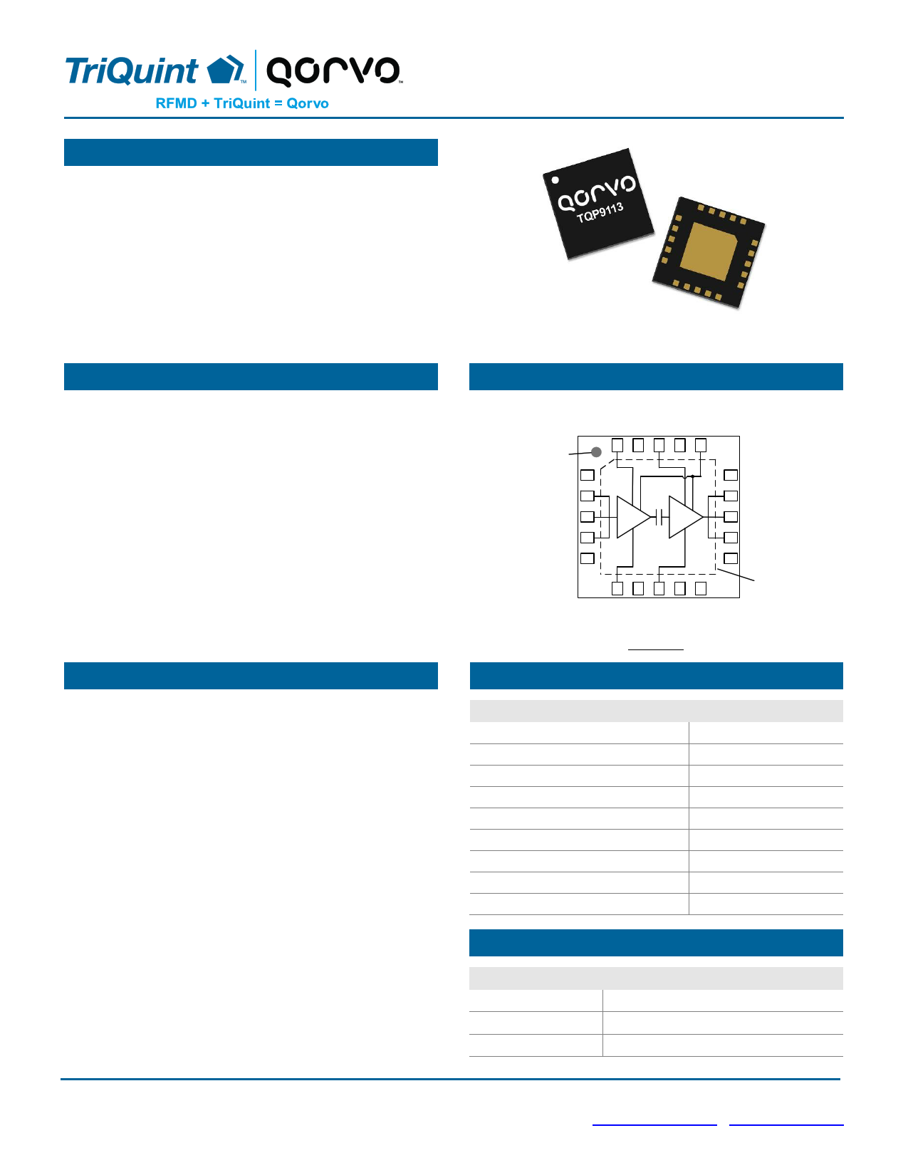
TQP9113
1 Watt Linear Amplifier
Product Features
1800 – 2700 MHz Frequency Range
27.6 dB Gain
+41 dBm Output IP3
+30.6 dBm P1dB
+5 V supply, 215 mA Current
Internal Input and Interstage Matching
Bias Adjustable
Power down functionality for TDD systems
20-Pin 4 x 4 mm Leadless QFN Package
Functional Block Diagram
Pin 1
Reference Mark
Package Topside
NC
RFin
RFin
RFin
NC
1
2
3
4
5
15 NC
14 RFout
13 RFout
12 RFout
11 NC
Exposed
Backside Pad
GND
General Description
The TQP9113 is a 1 W, linear, two-stage driver amplifier
in a low-cost surface-mount package. The amplifier is
able to achieve high performance with +41 dBm OIP3 and
+30.6 dBm P1dB while only consuming 215 mA current.
The input is internally matched and the amplifier only
requires only a few external components for operation.
The integrated interstage match minimizes performance
variation that would otherwise be attributed to external
matching component value and placement tolerances.
The TQP9113 is bias adjustable allowing the amplifier’s
power consumption to be reduced for occasions when
linear performance is not required. The amplifier can also
switched on and off for TDD applications. The output
match is tunable externally to allow the amplifier to be
optimized for high power or high linearity applications.
The TQP9113 is available in a RoHS-compliant 20-pin
4 x 4 mm surface mount package.
Top View
Pin Configuration
Pin No.
1, 5, 7, 9, 10, 11, 15, 17, 19
2, 3, 4
6
8
12, 13, 14
16
18
20
Backside Pad
Label
NC
RF in
IREF1
IREF2
RF out
VBIAS
VCC2
VCC1
GND
Ordering Information
Part No.
Description
TQP9113
1800 – 2700 MHz Linear Amplifier
TQP9113-PCB2140 1800 – 2200 MHz Evaluation Board
TQP9113-PCB2600 2300 – 2700 MHz Evaluation Board
Standard T/R size = 2,500 pieces on a 13” reel
Advanced Data Sheet: Rev. F 10-23-15
© 2015 TriQuint Semiconductor, Inc
- 1 of 13 -
Disclaimer: Subject to change without notice
www.triquint.com / www.qorvo.com
1 page 
TQP9113
1 Watt Linear Amplifier
Typical Performance TQP9113− PCB2140
Test conditions unless otherwise noted: VCC = +5 V, Vpd = +5 V, ICQ = 215 mA (typ.), Temp. = +25 °C
Parameter
Conditions
Typical Value
Frequency
1840
1960
2140
Gain
27.4 27.6 27.6
Input Return Loss
16 15 14
Output Return Loss
12 13 14
Output P1dB
+30.5
+30.6
+30.6
OIP3
Pout= +16 dBm/tone, Δf=1 MHz
+37 +39 +41
Noise Figure
5.2 4.9 4.7
WCDMA Channel Power(1)
−50 dBc ACLR
+17.9
+19.3
+18.4
Notes:
1. ACLR Test set-up: 3GPP WCDMA, TM1+64 DPCH, +5 MHz offset, PAR = 10.2 dB at 0.01% Probability
Units
MHz
dB
dB
dB
dBm
dBm
dB
dBm
Typical Performance TQP9113-PCB2140
Test conditions unless otherwise noted: VCC = +5 V, ICQ = 215 mA (typ.), Temp. = +25 °C
Gain vs. Frequency
29
Input Return Loss vs. Frequency
0
0
Output Return Loss vs. Frequency
-5
27
+105°C
+105°C
-10 +85°C
+25°C
+85°C
25 +25°C
−40°C
−40°C
-15
-5
+105°C
+85°C
-10 +25°C
−40°C
-15
23
1800
45
1900
2000
2100
Frequency (MHz)
OIP3 vs. Pout
2200
2300
Temp.=+25°C
-20
1800
45
1900
2000
2100
Frequency (MHz)
2200
OIP3 vs Output Power
2300
-20
1800
-40
1900
2000
2100
Frequency (MHz)
ACLR vs Pout
2200
Temp.=+25°C
2300
-45
40 40
+105°C
+85°C
-50
2140 MHz
+25°C
35
1960 MHz
35
−40°C
1840 MHz
-55
30
12 13 14 15 16 17 18 19
Pout (dBm/tone)
F = 2140 MHz
30
12 13 14 15 16 17 18 19
Pout (dBm/tone)
-60
16
ACLR vs. Pout
-35
ACLR vs Pout
-35
Temp.=+25°C
F = 2140 MHz
2140 MHz
1960 MHz
1840 MHz
W-CDMA 3GPP Test Model 1+64 DPCH
PAR = 10.2 dB at 0.01% Probability
3.84 MHz BW
17 18 19 20 21 22
Pout (dBm)
-40 2140 MHz
1960 MHz
1840 MHz
-45
-40 +105°C
+85°C
+25°C
−40°C
-45
-50
Signal : LTE 20MHz, PAR = 9.5dB
Channel BW E-UTRA, IBW = 18.02MHz
-55
16 17 18 19 20 21 22
Pout (dBm)
-50
Signal : LTE 20MHz, PAR = 9.5dB
Channel BW E-UTRA, IBW = 18.02MHz
-55
16 17 18 19 20 21 22
Pout (dBm)
Advanced Data Sheet: Rev. F 10-23-15
© 2015 TriQuint Semiconductor, Inc
- 5 of 13 -
Disclaimer: Subject to change without notice
www.triquint.com / www.qorvo.com
5 Page 
Pin Configuration and Description
TQP9113
1 Watt Linear Amplifier
Pin 1
Reference Mark
Package Topside
NC
RFin
RFin
RFin
NC
1
2
3
4
5
15 NC
14 RFout
13 RFout
12 RFout
11 NC
Exposed
Backside Pad
GND
Pin No.
1, 5, 7, 9, 10, 11,
15, 17, 19
2, 3, 4
6
8
12, 13, 14
16
18
20
Backside Pad
Label
NC
RF in
IREF1
IREF2
RF out
VBIAS
VCC2
VCC1
GND
Top View
Description
No internal connection. Provide grounded land pads for PCB mounting integrity.
RF input pins. Requires only DC blocking cap for operation.
Sets the bias current for Amp1. Also can be used to power down Amp 1.
Sets the bias current for Amp2. Also can be used to power down Amp 2.
RF output pins. Require DC blocking and RF match for optimal performance.
Bias circuit supply voltage.
2nd Stage DC voltage supply connection.
1st Stage DC voltage supply connection.
RF/DC ground. Use recommended via pattern to minimize inductance and thermal
resistance; see PCB Mounting Pattern for suggested footprint.
Evaluation Board PCB Information
TriQuint PCB 1100415 Material and Stack-up
0.014"
0.062" ± 0.006"
Finished Board
Thickness
Nelco N-4000-13
1 oz. Cu top layer
1 oz. Cu inner layer
Core
0.014"
Nelco N-4000-13
1 oz. Cu inner layer
1 oz. Cu bottom layer
50 ohm line dimensions: width = .028”
spacing = .028”.
Advanced Data Sheet: Rev. F 10-23-15
© 2015 TriQuint Semiconductor, Inc
- 11 of 13 -
Disclaimer: Subject to change without notice
www.triquint.com / www.qorvo.com
11 Page | ||
| Páginas | Total 13 Páginas | |
| PDF Descargar | [ Datasheet TQP9113.PDF ] | |
Hoja de datos destacado
| Número de pieza | Descripción | Fabricantes |
| TQP9111 | 2 Watt Power Amplifier | TriQuint Semiconductor |
| TQP9113 | 1 Watt Linear Amplifier | TriQuint Semiconductor |
| Número de pieza | Descripción | Fabricantes |
| SLA6805M | High Voltage 3 phase Motor Driver IC. |
Sanken |
| SDC1742 | 12- and 14-Bit Hybrid Synchro / Resolver-to-Digital Converters. |
Analog Devices |
|
DataSheet.es es una pagina web que funciona como un repositorio de manuales o hoja de datos de muchos de los productos más populares, |
| DataSheet.es | 2020 | Privacy Policy | Contacto | Buscar |