|
|
|
PDF NJU72040 Data sheet ( Hoja de datos )
| Número de pieza | NJU72040 | |
| Descripción | Ground Referenced Stereo Headphone Amplifier | |
| Fabricantes | New Japan Radio | |
| Logotipo | ||
Hay una vista previa y un enlace de descarga de NJU72040 (archivo pdf) en la parte inferior de esta página. Total 19 Páginas | ||
|
No Preview Available !
NJU72040
Ground Referenced Stereo Headphone Amplifier
GENERAL DESCRIPTION
The NJU72040 is an audio headphone amplifier .
Ground-referenced outputs eliminate output coupling
capacitor. The pop noise suppression circuit removes a pop
noise at the power-on and power-off.
It is suitable for audio headphone amplifer application
APPLICATIONS
q Audio applications which have audio headphone interface
s PACKAGE OUTLINE
NJU72040V
FEATURES
q Operating Voltage
q Operating Current
q Output Coupling Capacitor-less
q Pop Noise Suppression Circuit
q Gain Select
q C-MOS Technology
q Package Outline
+2.7 to +3.6V
IDD=10.5mA typ.
at V+=3.3V, No load, No Signal
SSOP14
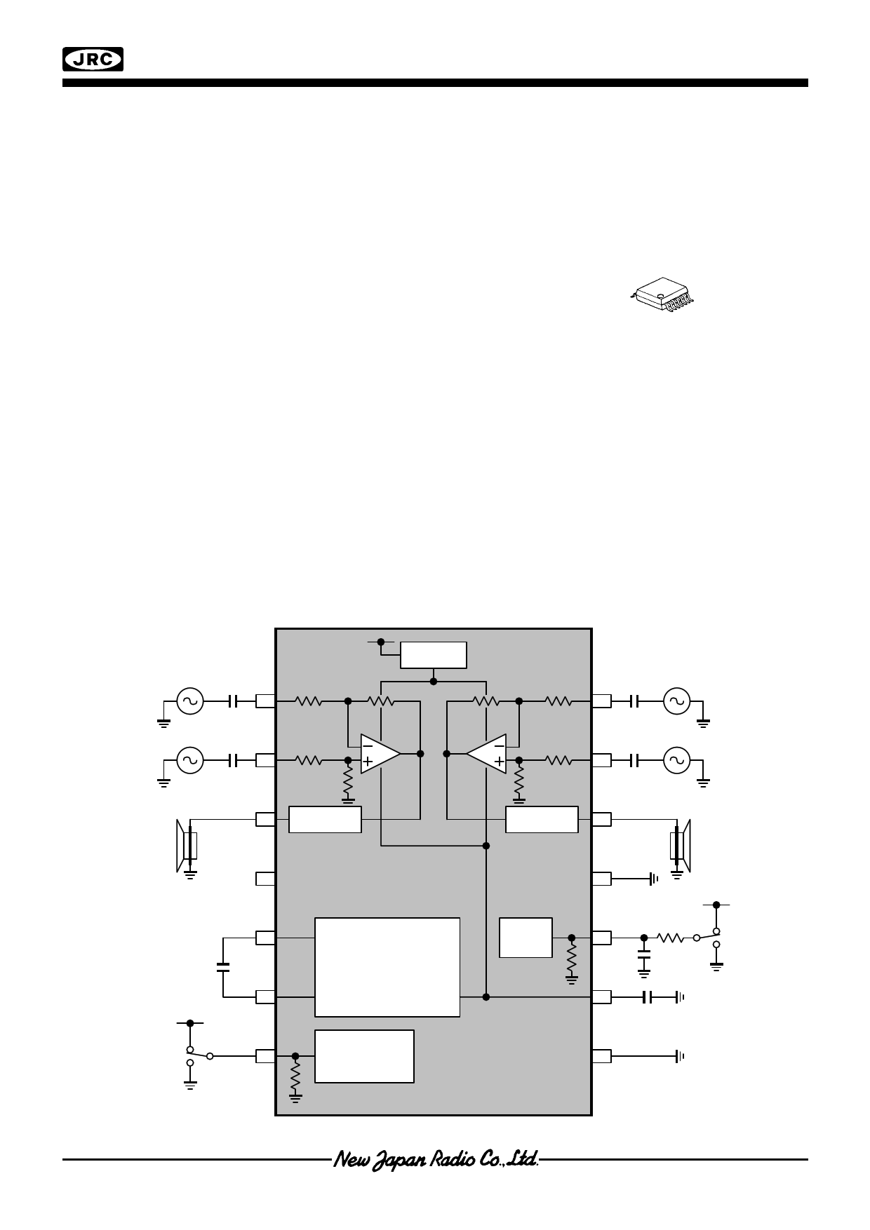
BLOCK DIAGRAM
inverted
phase
INL-
INL+
V+ Reg
V+ V+
INR-
INR+
inverted
phase
32Ω
Headphone
OUTL
V+
Pop Noise
Suppression
CP
Regulator
CN
Pop Noise
Suppression
OUTR
GND
Bias 3MΩ MUTE
V-
32Ω
Headphone
V+
GAIN 100kΩ
Gain Select
REF
Ver. 1.2E
–1–
1 page 
TEST CIRCUIT (POMAX2)
inverted phase INL-
V+
Regulator
C1=1uF
INL+
RL=32Ω
C2=1uF
OUTL
V
V+
Pop Noise
Suppression
CP
(*2)
C4=1uF
CN
Negative
Voltage
Regulator
GAIN 100kΩ
Gain Select
(*2): Monolithic Ceramic Capacitors
TEST CIRCUIT (VMUTE)
inverted phase INL-
V+
Regulator
C1=1uF
INL+
RL=32Ω
C2=1uF
OUTL
V
V+
Pop Noise
Suppression
CP
(*2)
C4=1uF
CN
Negative
Voltage
Regulator
GAIN 100kΩ
Gain Select
(*2): Monolithic Ceramic Capacitors
NJU72040
Pop Noise
Suppression
INR-
inverted phase
C10=1uF
INR+
C8=1uF
OUTR
RL=32Ω
GND
3MΩ MUTE
Bias
V+
V- (*2)
C6=10uF
REF
Pop Noise
Suppression
INR-
C10=1uF
INR+
C8=1uF
OUTR
GND
3MΩ MUTE
Bias
V- (*2)
C6=10uF
REF
RL=32Ω
–5–
5 Page 
NJU72040
1.2 Control of V+ terminal and Mute terminal
1.2.2 Power-on procedure
1. Turn on the V+.
2. After 5msec from power on, change the control voltage of MUTE terminal (Vcnt) from "Low" to "High".
* It is necessary to stabilize an IC for 5msec.
By releasing the MUTE function, the output terminal output the signal.
1.2.3 Power-off procedure
1. Change the control voltage of MUTE terminal (Vcnt) from "High" to "Low".
By the MUTE function, the output signals are stopped from output terminal.
2. Turn off the V+ after “2RC” sec from MUTE.
* It is necessary to stabilize a MUTE condition for “2RC” sec.
Ex.) R2=100kΩ, C7=1uF -> 2R2 x C7=200msec
V+
(4pin)
Vcnt
5msec
2RC=200msec
MUTE ON
MUTE
(10pin)
MUTE OFF
MUTE ON
Fig.5 Turn-on / Turn-off timing chart
t
t
t
– 11 –
11 Page | ||
| Páginas | Total 19 Páginas | |
| PDF Descargar | [ Datasheet NJU72040.PDF ] | |
Hoja de datos destacado
| Número de pieza | Descripción | Fabricantes |
| NJU72040 | Ground Referenced Stereo Headphone Amplifier | New Japan Radio |
| Número de pieza | Descripción | Fabricantes |
| SLA6805M | High Voltage 3 phase Motor Driver IC. |
Sanken |
| SDC1742 | 12- and 14-Bit Hybrid Synchro / Resolver-to-Digital Converters. |
Analog Devices |
|
DataSheet.es es una pagina web que funciona como un repositorio de manuales o hoja de datos de muchos de los productos más populares, |
| DataSheet.es | 2020 | Privacy Policy | Contacto | Buscar |