|
|
|
PDF LM2831 Data sheet ( Hoja de datos )
| Número de pieza | LM2831 | |
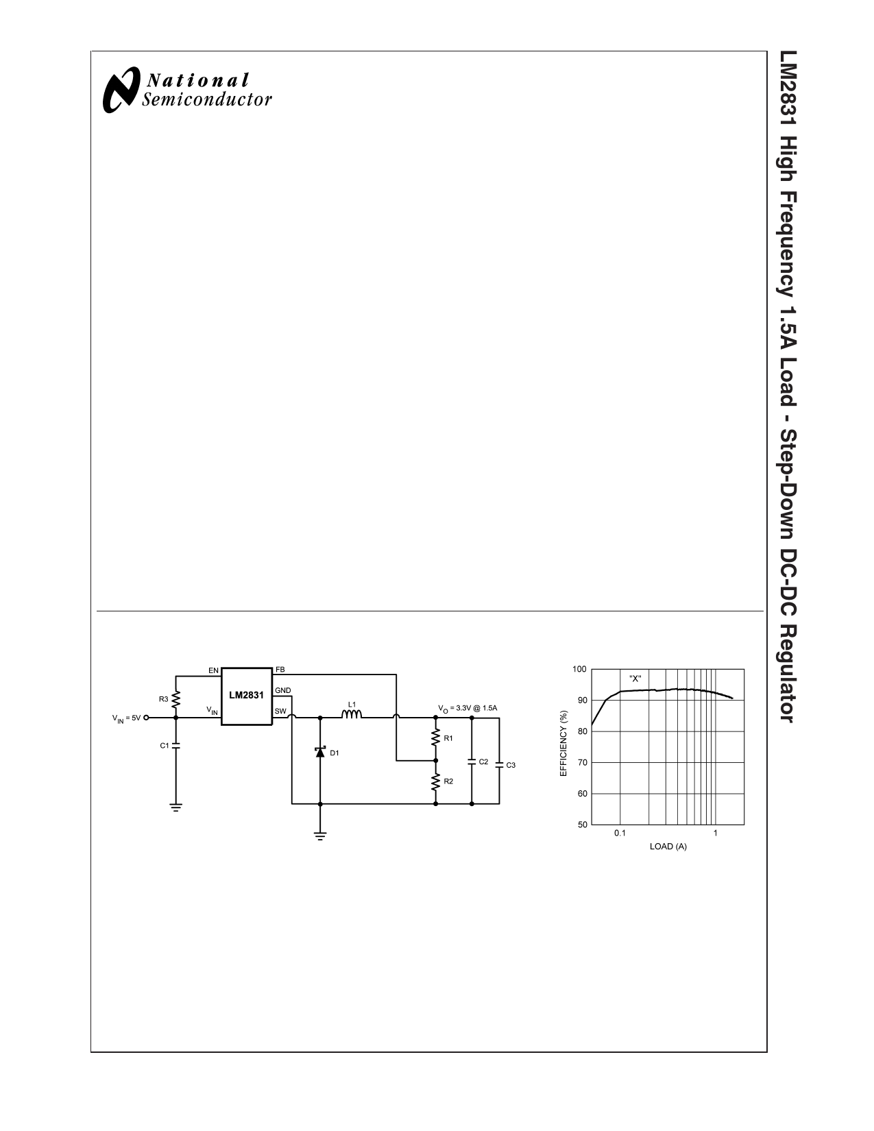
| Descripción | High Frequency 1.5A Load - Step-Down DC-DC Regulator | |
| Fabricantes | National Semiconductor | |
| Logotipo | ||
Hay una vista previa y un enlace de descarga de LM2831 (archivo pdf) en la parte inferior de esta página. Total 27 Páginas | ||
|
No Preview Available !
www.DataSheet4U.com
August 2006
LM2831
High Frequency 1.5A Load - Step-Down DC-DC
Regulator
General Description
The LM2831 regulator is a monolithic, high frequency, PWM
step-down DC/DC converter in a 5 pin SOT23 and a 6 Pin
LLP package. It provides all the active functions to provide
local DC/DC conversion with fast transient response and
accurate regulation in the smallest possible PCB area. With
a minimum of external components, the LM2831 is easy to
use. The ability to drive 1.5A loads with an internal 130 mΩ
PMOS switch using state-of-the-art 0.5 µm BiCMOS technol-
ogy results in the best power density available. The world-
class control circuitry allows on-times as low as 30ns, thus
supporting exceptionally high frequency conversion over the
entire 3V to 5.5V input operating range down to the minimum
output voltage of 0.6V. Switching frequency is internally set
to 550 kHz, 1.6 MHz, or 3.0 MHz, allowing the use of
extremely small surface mount inductors and chip capaci-
tors. Even though the operating frequency is high, efficien-
cies up to 93% are easy to achieve. External shutdown is
included, featuring an ultra-low stand-by current of 30 nA.
The LM2831 utilizes current-mode control and internal com-
pensation to provide high-performance regulation over a
wide range of operating conditions. Additional features in-
clude internal soft-start circuitry to reduce inrush current,
pulse-by-pulse current limit, thermal shutdown, and output
over-voltage protection.
Features
n Space Saving SOT23-5 Package
n Input voltage range of 3.0V to 5.5V
n Output voltage range of 0.6V to 4.5V
n 1.5A output current
n High Switching Frequencies
1.6MHz (LM2831X)
0.55MHz (LM2831Y)
3.0MHz (LM2831Z)
n 130mΩ PMOS switch
n 0.6V, 2% Internal Voltage Reference
n Internal soft-start
n Current mode, PWM operation
n Thermal Shutdown
n Over voltage protection
Applications
n Local 5V to Vcore Step-Down Converters
n Core Power in HDDs
n Set-Top Boxes
n USB Powered Devices
n DSL Modems
Typical Application Circuit
20174864
20174881
© 2006 National Semiconductor Corporation DS201748
www.national.com
1 page 
Electrical Characteristics VIN = 5V unless otherwise indicated under the Conditions column. Limits in
standard type are for TJ = 25˚C only; limits in boldface type apply over the junction temperature (TJ) range of -40˚C to
+125˚C. Minimum and Maximum limits are guaranteed through test, design, or statistical correlation. Typical values represent
the most likely parametric norm at TJ = 25˚C, and are provided for reference purposes only. (Continued)
Symbol
θJA
θJC
TSD
Parameter
Junction to Ambient
0 LFPM Air Flow (Note 3)
Junction to Case (Note 3)
Thermal Shutdown Temperature
Conditions
LLP-6 Package
SOT23-5 Package
LLP-6 Package
SOT23-5 Package
Min Typ Max Units
80
˚C/W
118
18
˚C/W
80
165 ˚C
Note 1: Absolute maximum ratings indicate limits beyond which damage to the device may occur. Operating Range indicates conditions for which the device is
intended to be functional, but does not guarantee specfic performance limits. For guaranteed specifications and test conditions, see the Electrical Characteristics.
Note 2: Thermal shutdown will occur if the junction temperature exceeds the maximum junction temperature of the device.
Note 3: Applies for packages soldered directly onto a 3” x 3” PC board with 2oz. copper on 4 layers in still air.
5 www.national.com
5 Page 
Applications Information
THEORY OF OPERATION
The LM2831 is a constant frequency PWM buck regulator IC
that delivers a 1.5A load current. The regulator has a preset
switching frequency of 550kHz, 1.6MHz, or 3.0MHz. This
high frequency allows the LM2831 to operate with small
surface mount capacitors and inductors, resulting in a
DC/DC converter that requires a minimum amount of board
space. The LM2831 is internally compensated, so it is simple
to use and requires few external components. The LM2831
uses current-mode control to regulate the output voltage.
The following operating description of the LM2831 will refer
to the Simplified Block Diagram (Figure 1) and to the wave-
forms in Figure 2. The LM2831 supplies a regulated output
voltage by switching the internal PMOS control switch at
constant frequency and variable duty cycle. A switching
cycle begins at the falling edge of the reset pulse generated
by the internal oscillator. When this pulse goes low, the
output control logic turns on the internal PMOS control
switch. During this on-time, the SW pin voltage (VSW) swings
up to approximately VIN, and the inductor current (IL) in-
creases with a linear slope. IL is measured by the current
sense amplifier, which generates an output proportional to
the switch current. The sense signal is summed with the
regulator’s corrective ramp and compared to the error am-
plifier’s output, which is proportional to the difference be-
tween the feedback voltage and VREF. When the PWM
comparator output goes high, the output switch turns off until
the next switching cycle begins. During the switch off-time,
inductor current discharges through the Schottky catch di-
ode, which forces the SW pin to swing below ground by the
forward voltage (VD) of the Schottky catch diode. The regu-
lator loop adjusts the duty cycle (D) to maintain a constant
output voltage.
OUTPUT OVERVOLTAGE PROTECTION
The over-voltage comparator compares the FB pin voltage
to a voltage that is 15% higher than the internal reference
VREF. Once the FB pin voltage goes 15% above the internal
reference, the internal PMOS control switch is turned off,
which allows the output voltage to decrease toward regula-
tion.
UNDERVOLTAGE LOCKOUT
Under-voltage lockout (UVLO) prevents the LM2831 from
operating until the input voltage exceeds 2.73V (typ). The
UVLO threshold has approximately 430 mV of hysteresis, so
the part will operate until VIN drops below 2.3V (typ). Hys-
teresis prevents the part from turning off during power up if
VIN is non-monotonic.
CURRENT LIMIT
The LM2831 uses cycle-by-cycle current limiting to protect
the output switch. During each switching cycle, a current limit
comparator detects if the output switch current exceeds 2.5A
(typ), and turns off the switch until the next switching cycle
begins.
THERMAL SHUTDOWN
Thermal shutdown limits total power dissipation by turning
off the output switch when the IC junction temperature ex-
ceeds 165˚C. After thermal shutdown occurs, the output
switch doesn’t turn on until the junction temperature drops to
approximately 150˚C.
Design Guide
INDUCTOR SELECTION
The Duty Cycle (D) can be approximated quickly using the
ratio of output voltage (VO) to input voltage (VIN):
The catch diode (D1) forward voltage drop and the voltage
drop across the internal PMOS must be included to calculate
a more accurate duty cycle. Calculate D by using the follow-
ing formula:
FIGURE 2. Typical Waveforms
20174866
SOFT-START
This function forces VOUT to increase at a controlled rate
during start up. During soft-start, the error amplifier’s refer-
ence voltage ramps from 0V to its nominal value of 0.6V in
approximately 600 µs. This forces the regulator output to
ramp up in a controlled fashion, which helps reduce inrush
current.
VSW can be approximated by:
VSW = IOUT x RDSON
The diode forward drop (VD) can range from 0.3V to 0.7V
depending on the quality of the diode. The lower the VD, the
higher the operating efficiency of the converter. The inductor
value determines the output ripple current. Lower inductor
values decrease the size of the inductor, but increase the
output ripple current. An increase in the inductor value will
decrease the output ripple current.
One must ensure that the minimum current limit (1.8A) is not
exceeded, so the peak current in the inductor must be
calculated. The peak current (ILPK) in the inductor is calcu-
lated by:
ILPK = IOUT + ∆iL
11 www.national.com
11 Page | ||
| Páginas | Total 27 Páginas | |
| PDF Descargar | [ Datasheet LM2831.PDF ] | |
Hoja de datos destacado
| Número de pieza | Descripción | Fabricantes |
| LM2830 | LM2830/-Q1 High-Frequency 1.0-A Load Step-Down DC-DC Regulator (Rev. E) | Texas Instruments |
| LM2830 | High Frequency 1.0A Load - Step-Down DC-DC Regulator | National Semiconductor |
| LM2830-Q1 | LM2830/-Q1 High-Frequency 1.0-A Load Step-Down DC-DC Regulator (Rev. E) | Texas Instruments |
| LM2831 | High Frequency 1.5A Load - Step-Down DC-DC Regulator (Rev. D) | Texas Instruments |
| Número de pieza | Descripción | Fabricantes |
| SLA6805M | High Voltage 3 phase Motor Driver IC. |
Sanken |
| SDC1742 | 12- and 14-Bit Hybrid Synchro / Resolver-to-Digital Converters. |
Analog Devices |
|
DataSheet.es es una pagina web que funciona como un repositorio de manuales o hoja de datos de muchos de los productos más populares, |
| DataSheet.es | 2020 | Privacy Policy | Contacto | Buscar |