|
|
|
PDF IRF640L Data sheet ( Hoja de datos )
| Número de pieza | IRF640L | |
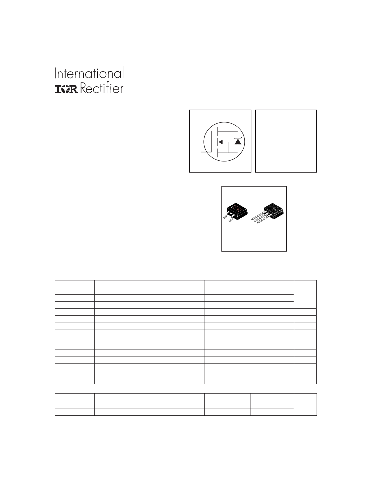
| Descripción | Power MOSFET(Vdss=200V/ Rds(on)=0.18ohm/ Id=18A) | |
| Fabricantes | International Rectifier | |
| Logotipo | ||
Hay una vista previa y un enlace de descarga de IRF640L (archivo pdf) en la parte inferior de esta página. Total 10 Páginas | ||
|
No Preview Available !
l Surface Mount (IRF640S)
l Low-profile through-hole (IRF640L)
l Available in Tape & Reel (IRF640S)
l Dynamic dv/dt Rating
l 150°C Operating Temperature
l Fast Switching
l Fully Avalanche Rated
G
Description
Third Generation HEXFETsfrom InternationalRectifier provide
the designer with the best combinations of fast switching ,
ruggedized device design, low on-resistance and cost-
effectiveness.
The D2Pak is a surface mount power package capable of
accommodating die sizes up to HEX-4. It provides the highest
power capability and the lowest possible on-resistance in any
existing surface mount package. The D2Pak is suitable for high
current applications because of its low internal connection
resistance and can dissipate up to 2.0W in a typical surface
mount application.The through-hole version (IRF640L) is
available for low-profile applications.
Absolute Maximum Ratings
ID @ TC = 25°C
ID @ TC = 100°C
IDM
PD @TA = 25°C
PD @TC = 25°C
VGS
EAS
IAR
EAR
dv/dt
TJ
TSTG
Parameter
Continuous Drain Current, VGS @ 10V
Continuous Drain Current, VGS @ 10V
Pulsed Drain Current
Power Dissipation
Power Dissipation
Linear Derating Factor
Gate-to-Source Voltage
Single Pulse Avalanche Energy
Avalanche Current
Repetitive Avalanche Energy
Peak Diode Recovery dv/dt
Operating Junction and
Storage Temperature Range
Soldering Temperature, for 10 seconds
Thermal Resistance
RθJC
RθJA
www.irf.com
Parameter
Junction-to-Case
Junction-to-Ambient ( PCB Mounted,steady-state)**
PD -90902B
IRF640S/L
HEXFET® Power MOSFET
D
VDSS = 200V
RDS(on) = 0.18Ω
ID = 18A
S
D 2 Pak
T O -26 2
Max.
18
11
72
3.1
130
1.0
± 20
580
18
13
5.0
-55 to + 175
300 (1.6mm from case )
Typ.
–––
–––
Max.
1.0
40
Units
A
W
W
W/°C
V
mJ
A
mJ
V/ns
°C
Units
°C/W
1
7/20/99
1 page 
Fig 9. Maximum Drain Current Vs.
Case Temperature
IRF640S/L
VDS
VGS
RG
RD
D.U.T.
10V
Pulse Width ≤ 1 µs
Duty Factor ≤ 0.1 %
+-VDD
Fig 10a. Switching Time Test Circuit
VDS
90%
10%
VGS
td(on) tr
td(off) tf
Fig 10b. Switching Time Waveforms
Fig 11. Maximum Effective Transient Thermal Impedance, Junction-to-Case
www.irf.com
5
5 Page | ||
| Páginas | Total 10 Páginas | |
| PDF Descargar | [ Datasheet IRF640L.PDF ] | |
Hoja de datos destacado
| Número de pieza | Descripción | Fabricantes |
| IRF640 | N-channel TrenchMOS transistor | NXP Semiconductors |
| IRF640 | N-CHANNEL 200V, 18A, MOSFET ( TO-220/TO-220FP ) | STMicroelectronics |
| IRF640 | Power MOSFET(Vdss=200V/ Rds(on)=0.18ohm/ Id=18A) | International Rectifier |
| IRF640 | 200V N-Channel MOSFET | Fairchild Semiconductor |
| Número de pieza | Descripción | Fabricantes |
| SLA6805M | High Voltage 3 phase Motor Driver IC. |
Sanken |
| SDC1742 | 12- and 14-Bit Hybrid Synchro / Resolver-to-Digital Converters. |
Analog Devices |
|
DataSheet.es es una pagina web que funciona como un repositorio de manuales o hoja de datos de muchos de los productos más populares, |
| DataSheet.es | 2020 | Privacy Policy | Contacto | Buscar |