|
|
|
PDF AD5175 Data sheet ( Hoja de datos )
| Número de pieza | AD5175 | |
| Descripción | Digital Rheostat with I2C Interface and 50-TP Memory | |
| Fabricantes | Analog Devices | |
| Logotipo | ||
Hay una vista previa y un enlace de descarga de AD5175 (archivo pdf) en la parte inferior de esta página. Total 20 Páginas | ||
|
No Preview Available !
www.DataSheet4U.com
Single-Channel, 1024-Position, Digital Rheostat
with I2C Interface and 50-TP Memory
AD5175
FEATURES
Single-channel, 1024-position resolution
10 kΩ nominal resistance
50-times programmable (50-TP) wiper memory
Rheostat mode temperature coefficient: 35 ppm/°C
2.7 V to 5.5 V single-supply operation
±2.5 V to ±2.75 V dual-supply operation for ac or bipolar
operations
I2C-compatible interface
Wiper setting and memory readback
Power on refreshed from memory
Resistor tolerance stored in memory
Thin LFCSP, 10-lead, 3 mm × 3 mm × 0.8 mm package
Compact MSOP, 10-lead 3 mm × 4.9 mm × 1.1 mm package
APPLICATIONS
Mechanical rheostat replacements
Op-amp: variable gain control
Instrumentation: gain, offset adjustment
Programmable voltage to current conversions
Programmable filters, delays, time constants
Programmable power supply
Sensor calibration
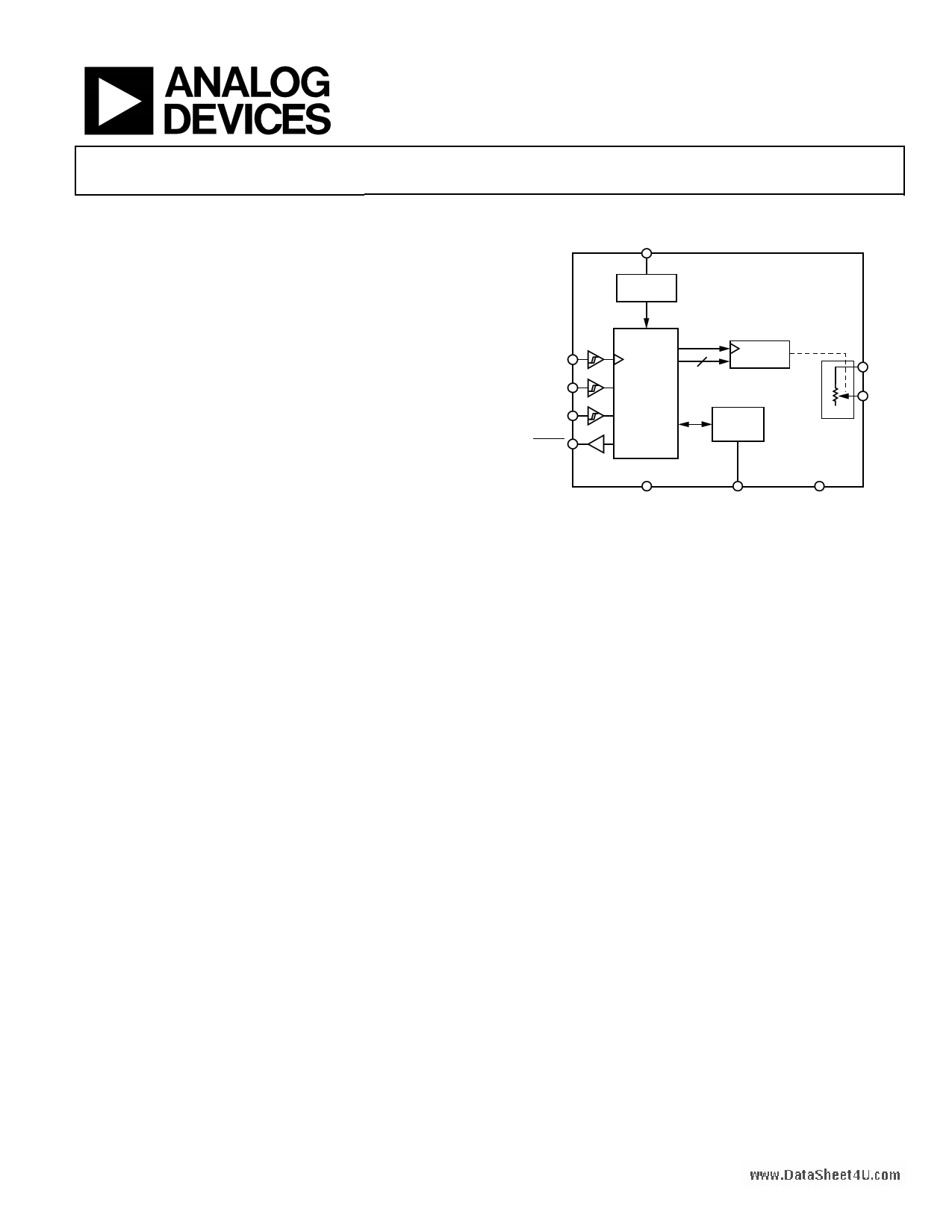
FUNCTIONAL BLOCK DIAGRAM
VDD
POWER-ON
RESET
AD5175
SCL
SDA
ADDR
RESET
I2C
SERIAL
INTERFACE
RDAC
REGISTER
10
50-TP
MEMORY
BLOCK
A
W
VSS EXT_CAP
Figure 1.
GND
GENERAL DESCRIPTION
The AD5175 is a single-channel, 1024-position digital rheostat
that combines industry leading variable resistor performance
with nonvolatile memory (NVM) in a compact package.
This device supports both dual-supply operation at ±2.5 V to
±2.75 V and single-supply operation at 2.7 V to 5.5 V, and offers
50-times programmable (50-TP) memory.
The AD5175 device wiper settings are controllable through the
I2C–compatible digital interface. Unlimited adjustments are
allowed before programming the resistance value into the
50-TP memory. The AD5175 does not require any external
voltage supply to facilitate fuse blow and there are 50 oppor-
tunities for permanent programming. During 50-TP activation,
a permanent blow fuse command freezes the resistance position
(analogous to placing epoxy on a mechanical rheostat).
The AD5175 is available in a 3 mm × 3mm 10-lead LFCSP
package and in a 10-lead MSOP package. The part is guaranteed
to operate over the extended industrial temperature range of
−40°C to +125°C.
Rev. 0
Information furnished by Analog Devices is believed to be accurate and reliable. However, no
responsibility is assumed by Analog Devices for its use, nor for any infringements of patents or other
rights of third parties that may result from its use. Specifications subject to change without notice. No
license is granted by implication or otherwise under any patent or patent rights of Analog Devices.
Trademarksandregisteredtrademarksarethepropertyoftheirrespectiveowners.
One Technology Way, P.O. Box 9106, Norwood, MA 02062-9106, U.S.A.
Tel: 781.329.4700
www.analog.com
Fax: 781.461.3113
©2010 Analog Devices, Inc. All rights reserved.
1 page 
AD5175www.DataSheet4U.com
Parameter
tRDAC_R-PERF
tRDAC_NORMAL
tMEMORY_READ
tMEMORY_PROGRAM
tRESET
tPOWER-UP 6
Conditions1
Limit at TMIN, TMAX
Min Max
Unit Description
2 μs RDAC register write command execute time (R-Perf mode)
600 ns RDAC register write command execute time (normal mode)
6 μs Memory readback execute time
350 ms Memory program time
600 μs Reset 50-TP restore time
2 ms Power-on 50-TP restore time
1 Maximum bus capacitance is limited to 400 pF.
2 The SDA and SCL timing is measured with the input filters enabled. Switching off the input filters improves the transfer rate but has a negative effect on EMC behavior
of the part.
3 Input filtering on the SCL and SDA inputs suppresses noise spikes that are less than 50 ns for fast mode.
4 Refer to tRDAC_R-PERF and tRDAC_NORMAL for RDAC register write operations.
5 Refer to tMEMORY_READ and tMEMORY_PROGRAM for memory commands operations.
6 Maximum time after VDD − VSS is equal to 2.5 V.
Shift Register and Timing Diagrams
DB9 (MSB)
DB0 (LSB)
0 0 C3 C2 C1 C0 D9 D8 D7 D6 D5 D4 D3 D2 D1 D0
CONTROL BITS
DATA BITS
Figure 2. Shift Register Content
SCL
t6
SDA
t7
PS
RESET
t11
t2
t4
t12
t1
t3
t6
t5 t10
S
Figure 3. 2-Wire I2C Timing Diagram
t8
t9
P
t13
Rev. 0 | Page 5 of 20
5 Page 
TEST CIRCUITS
Figure 20 to Figure 24 define the test conditions used in the Specifications section.
DUT
W
A
IW
VMS
Figure 20. Resistor Position Nonlinearity Error
(Rheostat Operation; R-INL, R-DNL)
AD5175www.DataSheet4U.com
DUT
W
A
1GΩ
VMS
V
Figure 23. Gain vs. Frequency
DUT
CODE = 0x00
W
RWA
=
VMS
IW
IW
RW
=
RWA
2
A
VMS
Figure 21. Wiper Resistance
DUT
W
A
ICM
GND
+2.75V
–2.75V
GND
NC
+2.75V
GND
–2.75V
NC = NO CONNECT
Figure 24. Common Leakage Current
V+
VDD
W
A
V+ = VDD ±10%
PSRR (dB) = 20 log
VMS
VDD
IW
PSS
(%/%)
=
ΔVMS%
ΔVDD%
VMS
Figure 22. Power Supply Sensitivity (PSS, PSRR)
Rev. 0 | Page 11 of 20
11 Page | ||
| Páginas | Total 20 Páginas | |
| PDF Descargar | [ Datasheet AD5175.PDF ] | |
Hoja de datos destacado
| Número de pieza | Descripción | Fabricantes |
| AD5170 | I2C Digital Potentiometer | Analog Devices |
| AD5171 | 64-Position OTP Digital Potentiometer | Analog Devices |
| AD5172 | Dual-Channel I2C Digital Potentiometers | Analog Devices |
| AD5173 | Dual-Channel I2C Digital Potentiometers | Analog Devices |
| Número de pieza | Descripción | Fabricantes |
| SLA6805M | High Voltage 3 phase Motor Driver IC. |
Sanken |
| SDC1742 | 12- and 14-Bit Hybrid Synchro / Resolver-to-Digital Converters. |
Analog Devices |
|
DataSheet.es es una pagina web que funciona como un repositorio de manuales o hoja de datos de muchos de los productos más populares, |
| DataSheet.es | 2020 | Privacy Policy | Contacto | Buscar |