|
|
|
PDF M-8870-01SM Data sheet ( Hoja de datos )
| Número de pieza | M-8870-01SM | |
| Descripción | DTMF Receiver | |
| Fabricantes | Clare Inc. | |
| Logotipo | ||
Hay una vista previa y un enlace de descarga de M-8870-01SM (archivo pdf) en la parte inferior de esta página. Total 9 Páginas | ||
|
No Preview Available !
Features
• Low Power Consumption
• Adjustable Acquisition and Release Times
• Central Office Quality and Performance
• Power-down and Inhibit Modes (-02 only)
• Inexpensive 3.58 MHz Time Base
• Single 5 Volt Power Supply
• Dial Tone Suppression
Applications
• Telephone switch equipment
• Remote data entry
• Paging systems
• Personal computers
• Credit card systems
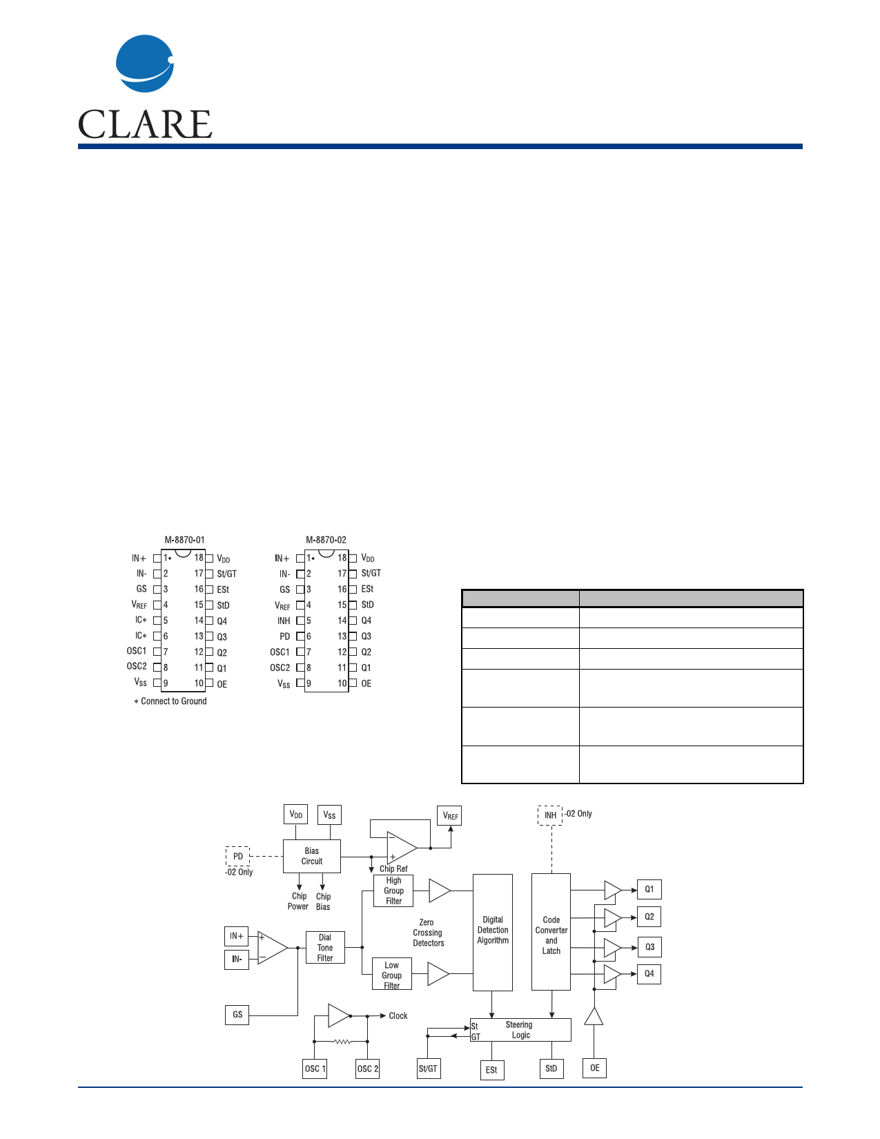
Pin Configuration
Block Diagram
M-8870
DTMF Receiver
Description
The M-8870 is a full DTMF Receiver that integrates
both bandsplit filter and decoder functions into a single
18-pin DIP or SOIC package. Manufactured using
CMOS process technology, the M-8870 offers low
power consumption (35 mW max) and precise data
handling. Its filter section uses switched capacitor
technology for both the high and low group filters and
for dial tone rejection. Its decoder uses digital counting
techniques to detect and decode all 16 DTMF tone
pairs into a 4-bit code. External component count is
minimized by provision of an on-chip differential input
amplifier, clock generator, and latched tri-state inter-
face bus. Minimal external components required
include a low-cost 3.579545 MHz color burst crystal, a
timing resistor, and a timing capacitor.
The M-8870-02 provides a “power-down” option
which, when enabled, drops consumption to less
than 0.5 mW. The M-8870-02 can also inhibit the
decoding of fourth column digits (see Tone Decoding
table on page 5).
Ordering Information
Part #
M-8870-01
Description
18-pin plastic DIP
M-8870-01SM 18-pin plastic SOIC
M-8870-01SMTR 18-pin plastic SOIC, tape and reel
M-8870-02
18-pin plastic DIP, power-down,
option
M-8870-02SM
18-pin plastic SOIC, power-down,
option
M-8870-02T
18-pin plastic SOIC, power-down
option, tape and reel
DS-M8870-R3
www.clare.com
1
1 page 
stops the oscillator and the functioning of the filters.
On the M-8870-01 models, this pin is tied to ground
(logic low).
Inhibit mode is enabled by a logic high input to pin 5
(INH). It inhibits the detection of 1633 Hz. The output
code will remain the same as the previous detected
code (see Pin functions table on page 4). On the M-
8870-01 models, this pin is tied to ground (logic low).
Input Configuration
The input arrangement of the M-8870 provides a dif-
ferential input operational amplifier as well as a bias
source (VREF) to bias the inputs at mid-rail. Provision
is made for connection of a feedback resistor to the
op-amp output (GS) for gain adjustment.
Tone Decoding
FLOW
697
FHIGH
1209
Key (ref.)
1
697 1336
697 1477
770 1209
2
3
4
770 1336
770 1477
852 1209
5
6
7
852 1336
852 1477
941 1336
8
9
0
941 1209
941 1477
697 1633
S
#
A
770 1633
852 1633
941 1633
B
C
D
ANY ANY
ANY
L = logic low, H = logic high, Z = high impedance
Differential Input Configuration
OE
H
H
H
H
H
H
H
H
H
H
H
H
H
H
H
H
L
M-8870
In a single-ended configuration, the input pins are
connected as shown in the Single - Ended Input
Configuration on page 3 with the op-amp connected
for unity gain and VREF biasing the input at 1/2VDD.
The Differential Input Configuration bellow permits
gain adjustment with the feedback resistor R5.
DTMF Clock Circuit
The internal clock circuit is completed with the addition
of a standard 3.579545 MHz television color burst crys-
tal. The crystal can be connected to a single M-8870 as
shown in the Single - Ended Input Configuration on
page 3, or to a series of M-8870s. As illustrated in the
Common Crystal Connection below, a single crystal
can be used to connect a series of M-8870s by cou-
pling the oscillator output of each M-8870 through a 30
pF capacitor to the oscillator input of the next M-8870.
Q4 Q3 Q2 Q1
0 001
0 010
0 011
0 100
0 101
0 110
0 111
1 000
1 001
1 010
1 011
1 100
1 101
1 110
1 111
0 000
Z ZZZ
Common Crystal Connection
Rev. 3 www.clare.com
5
5 Page | ||
| Páginas | Total 9 Páginas | |
| PDF Descargar | [ Datasheet M-8870-01SM.PDF ] | |
Hoja de datos destacado
| Número de pieza | Descripción | Fabricantes |
| M-8870-01SM | DTMF Receiver | Clare Inc. |
| M-8870-01SMTR | DTMF Receiver | Clare Inc. |
| Número de pieza | Descripción | Fabricantes |
| SLA6805M | High Voltage 3 phase Motor Driver IC. |
Sanken |
| SDC1742 | 12- and 14-Bit Hybrid Synchro / Resolver-to-Digital Converters. |
Analog Devices |
|
DataSheet.es es una pagina web que funciona como un repositorio de manuales o hoja de datos de muchos de los productos más populares, |
| DataSheet.es | 2020 | Privacy Policy | Contacto | Buscar |